Technical Information 6 720 642 841-00.
Contents Contents 1 Explanation of symbols and safety instructions . . . . . . . . . . . . . . . . . . . . . . . . . . . . . . . 4 1.1 Guideline to symbols . . . . . . . . . . . . . . . . . . . . . . . . . . . . . . . . . . . . . . . . . . . . . . . . . . . . . . 4 1.2 Safety instructions . . . . . . . . . . . . . . . . . . . . . . . . . . . . . . . . . . . . . . . . . . . . . . . . . . . . . . . . 5 2 Product description . . . . . . . . . . . . . . . . . . . . . . . . . . . . . . . . . . . . . . . . .
Contents 4 Operating basics . . . . . . . . . . . . . . . . . . . . . . . . . . . . . . . . . . . . . . . . . . . . . . . . . . . . . . . . . 38 5 Incorporation of Logamatic 4000 in LON networks via Logamatic LON-Gateway . . . . . . . . . . . . . . . . . . . . . . . . . . . . . . . . . . . . . . . . . . . . . . . . . . . 39 5.1 Structure of the hardware . . . . . . . . . . . . . . . . . . . . . . . . . . . . . . . . . . . . . . . . . . . . . . . . . . 39 5.2 Creating LON networks . . . . . . . . . . . .
Explanation of symbols and safety instructions 1 1 Explanation of symbols and safety instructions 1.1 Guideline to symbols Warnings Warnings are indicated in the text by a warning triangle and a gray background. In case of danger from electric shock, the exclamation point on the warning triangle is replaced with a lightning symbol. Signal words at the beginning of a warning are used to indicate the type and seriousness of the ensuing risk if measures for minimizing damage are not taken.
Explanation of symbols and safety instructions 1 WARNING: Only transformers with following specification are permitted: 6 V AC; 400 mA. The transformer is not part of the product! Please take care to use a reliable product which meets our requirements shown above. Do not mount the transformer internally! Buderus does not accept responsibility for systems which contravene the Installation instruction or addition documentation in scope of delivery.
2 2 Product description Product description 2.1 Correct use The Logamatic LON-Gateway may only be used to connect Buderus boilers with control panel from the Buderus Logamatic 4000 control series to superior control and/or building control systems via LON-BUS. 2.2 Disposal B Electronic components do not belong in household waste. Dispose of defunct modules correctly through an authorized disposal site.
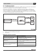
Product description 2 2.3 Product description The Logamatic LON-Gateway is incorporated into a LON network via a twisted pair cable (twisted 2-wire line). The twisted pair cable is protected against reverse polarity. Defined data of the Buderus control panel is implemented with the Logamatic LON-Gateway interface on standard network variable types (SNVTs) for the LON data bus.
2 Product description Product features of the LON-Gateway • Can be used with all digital Logamatic 4000 control panels • Interface can be equipped after the fact for the superior control system or for LON thermostats, integration into existing building control technology/direct digital control (GLT/DDC) • Interoperability through use of the standard network variable types (SNVT) assured according to LonMark® • Provision of the SNVT data for systems consisting of: Communication objects Boiler Heating zones
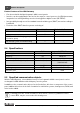
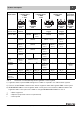
Product description Requirement 2 1 boiler 5 heating zones 1 DHW 1 solar 2 boiler 5 heating zones 1 DHW 1 solar 4 boilers 1 heating zone 1 DHW Expansion for heating zones 3, 4 1) Logamatic 4211 Logamatic 4121 Logamatic 4321 Logamatic 4323 Logamatic 4122 Boiler with Logamatic 4000 y (ZM422) – o 2) (FM458) o2) (FM458) – Boiler with Logamatic EMS – o2) (FM458) o2) (FM458) – o (FM441 in slot 2) o (FM441 in slot 1) – y (ZM424) o (FM456 in slot 2) y (ZM422) y (ZM424) LON HK 1 o (FM4
2 Product description 2.6 Logamatic LON-Gateway firmware 2.6.1 Firmware when delivered When delivered, the firmware version LON_Flasher_2B_00 is preinstalled. This version is for a heating system with floor-standing boilers with Logamatic 4321. If you need another firmware variant (e.g. LON_Flasher_4B_00) for your installation, it is easy to update the firmware.
Network interface 3 3 Network interface 3.1 Overview of the SNVTs for variant 2 boilers The prerequisite for the proper function is that the firmware on the LON-Gateway interface has at least the version number indicated below and the following application file is used: Alternative Buderus (alternative of the LON-Flasher) LON application file (XIF file) 2 boilers with Logamatic EMS LON_Flasher_2B_E_00 LON_2B_00 2 boilers with Logamatic 4000 LON_Flasher_2B_00 LON_2B_00 Tab.
Network interface 3 No.
Network interface No.
3 Network interface 3.2 Description of the SNVTs for variant 2 boilers Note: The right column indicates the number of bytes. 3.2.1 General 0 Tab. 8 Time SNVT_time_ stamp(84) nviUhrzeit 7 Value for comparison of the time in the Buderus control system with the LON network Format: YYYY/MM/DD hh:mm:ss 1 Tab. 9 Outdoor temperature SNVT_temp_p(105) nvoAussen_Tp 2 Display of the current outdoor temperature Note: 230 °F (110 °C) is an invalid value (e.g.
Network interface 3 Example: 3 Error message 2 control panel address 1 + 2 SNVT_state(83) nvoFehler1 2 4 Error message 3 control panel address 1 + 2 SNVT_state(83) nvoFehler1 2 5 Error message 4 control panel address 1 + 2 SNVT_state(83) nvoFehler1 2 Tab. 12 Outputs for error messages Second, third, and fourth current errors in the control panel in question. List of the error list, see Chapter 7, page 43. Interpretation as described for error message 1.
Network interface 3 3.2.2 Heating zones This section describes only heating zone 1. For heating zones 2 to 5, the details apply accordingly. 6 Operating mode (Day/Night/Auto) Tab. 13 SNVT_hvac_mode (108) nviHK1TgNtAt 1 Value for changing the operating mode of a heating zone Format: Value Designation Description 0 HVAC_AUTO The heating zone is controlled according to the set heating program (automatic mode). 1 HVAC_heat The heating zone is controlled in day mode (manual day mode).
Network interface 3 Notes: • The room set point night temperature specifies the temperature level in the setback mode or night mode for the consumer. With this setting, the heating curve moves in parallel. If you change the room set point temperature by 2 °F (1 °C), then the supply temperature changes by approx. 6 °F (3 °C). • The room set point night temperature is not active with the setback type "off.
3 Network interface 3.2.3 DHW heating 36 Tab. 20 Operating mode (Day/Night/ Auto) SNVT_hvac_mode (108) nviHK1TgNtAt 1 Value for changing the operating mode of DHW heating Format: Value Designation Description 0 HVAC_AUTO The DHW control follows the set DHW program (automatic mode). 1 HVAC_heat The DHW control operates in constant operation (manual day mode). 6 HVAC_off The DHW controls are turned off (manual night mode). Tab.
Network interface 3 Format: Value Designation Description 0 HVAC_AUTO The activation of the recirculation pump works according to the recirculation pump program set (automatic mode). 1 HVAC_heat The recirculation pump is activated constantly (manual day mode). 6 HVAC_off The recirculation pump is turned off (manual night mode). Tab. 24 Changing the operating mode With the HVAC_heat / HVAC_off setting, the operating mode for the consumer is changed externally via the LON data bus. 39 Tab.
Network interface 3 3.2.4 Strategy In the "Strategy" section, the values for the entire heating system are summarized. This is especially important for multi-boiler systems (cascades). 43 Operating mode (D/N/A) system Tab. 29 SNVT_hvac_mode (108) nviAnl_TgNtAt 2 Value for changing the operating mode of the entire system (all heating zones) Format: Value Designation Description 0 HVAC_AUTO The system works according to the internal setting on the control panel (automatic mode).
Network interface 3 3.2.5 Floor-standing boilers This section describes "floor-standing boiler 1." For boiler 2, the details apply accordingly. 47 Tab.
Network interface 3 3.2.6 Solar 53 Solar operating mode (Day/Night/ Auto) Tab. 38 SNVT_hvac_mode (108) nviSLTgNtAt 2 Value for changing the operating mode of the solar heating system Format: Value Designation Description 0 HVAC_AUTO The solar thermal system works according to the internal setting on the control panel (automatic mode). 1 HVAC_heat The solar thermal system is turned on and works in manual day mode (heed instructions - no control function!).
Network interface 3 3.3 Overview of the SNVTs for variant 4 boilers The prerequisite for the proper function is that the firmware on the LON-Gateway interface has at least the version number indicated below and the following application file is used: Alternative 4 boilers with Logamatic EMS or Logamatic 4000 Buderus (alternative of the LON-Flasher) LON application file (XIF file) LON_Flasher_4B 00 LON_4B_00 Tab.
Network interface 3 No.
Network interface No.
3 Network interface 3.4 Description of the SNVTs for variant 4 boilers 3.4.1 General 0 Tab. 46 Time SNVT_time_ stamp(84) nviUhrzeit 7 Value for comparison of the time in the Buderus control system with the LON network Format: YYYY/MM/DD hh:mm:ss 1 Tab. 47 Outdoor temperature SNVT_temp_p(105) nvoAussen_Tp 2 Display of the current outdoor temperature Note: 230 °F (110 °C) is an invalid value (e.g. no temperature sensor connected, sensor defective, etc.
Network interface 3 Example: nvoFehler changes On the display, you see: nvoFehler1 0 0 0 0 0 0 0 0 1 0 0 0 1 1 0 0 Tab. 50 Boiler 2 has no error. Boiler 1 has a fault with the following error number: nvoFehler1 0 0 0 0 0 0 0 0 1 0 0 0 1 1 0 0 Interpretation 20 21 22 23 24 25 26 27 20 21 22 23 24 25 26 27 16 32 Meaning 1 Tab. 51 Boiler 1 has the error no.
3 Network interface 3.4.2 Heating zones This section describes only heating zone 1. 10 Tab. 54 Operating mode (Day/Night/ Auto) SNVT_hvac_mode (108) nviHK1TgNtAt 1 Value for changing the operating mode of a heating zone Format: Value Designation Description 0 HVAC_AUTO The heating zone is controlled according to the set heating program (automatic mode). 1 HVAC_heat The heating zone is controlled in day mode (manual day mode).
Network interface 3 Notes: • The room set point night temperature specifies the temperature level in the setback mode or night mode for the consumer. With this setting, the heating curve moves in parallel. If you change the room set point temperature by 2 °F (1 °C), then the supply temperature changes by approx. 6 °F (3 °C). • The room set point night temperature is not active with the setback type "off.
3 Network interface 3.4.3 DHW heating 16 Tab. 61 Operating mode (D/N/A) SNVT_hvac_mode (108) nviHK1TgNtAt 1 Value for changing the operating mode of DHW heating Format: Value Designation Description 0 HVAC_AUTO The DHW control follows the set DHW program (automatic mode). 1 HVAC_heat The DHW control operates in constant operation (manual day mode). 6 HVAC_off The DHW controls are turned off (manual night mode).
Network interface 3 Format: Value Designation Description 0 HVAC_AUTO The activation of the recirculation pump works according to the recirculation pump program set (automatic mode). 1 HVAC_heat The recirculation pump is activated constantly (manual day mode). 6 HVAC_off The recirculation pump is turned off (manual night mode). Changing the operating mode With the HVAC_heat / HVAC_off setting, the operating mode for the consumer is changed externally via the LON data bus. 19 Tab. 64 20 Tab.
Network interface 3 3.4.4 Strategy In the "Strategy" section, the values for the entire heating system are summarized. This is especially important for multi-boiler systems (cascades). 23 Operating mode (D/N/A) system Tab. 68 SNVT_hvac_mode (108) nviAnl_TgNtAt 2 Value for changing the operating mode of the entire system (all heating zones) Format: Value Designation Description 0 HVAC_AUTO The system works according to the internal setting on the control panel (automatic mode).
Network interface 3 3.4.5 Boiler 1 This section describes "boiler 1." 28 Status burner 4000 boiler 1 Tab. 73 SNVT_lev_cont (21) nvoKS1_Br_4000 2 Indicator for boiler 1 with Logamatic 4000 and third party burner Burner OFF [0 %] ON [> 0 %] Current output [%] 29 Temperature 4000 boiler 1 (FK) actual Tab. 74 SNVT_temp_p(105) nvoKS1VLIst_4000 2 Display of the current boiler temperature for boiler 1 with Logamatic 4000 and third party burner Note: 230 °F (110 °C) is an invalid value (e.g.
Network interface 3 33 Pump 4000 boiler 1 Tab. 78 SNVT_lev_cont (21) nvoKS1PU_4000 2 Indicator for boiler 1 with Logamatic 4000 and third party burner Pump OFF [0 %] ON [> 0 %] Current output [%] 34 Status burner EMS boiler 1 Tab. 79 SNVT_lev_cont (21) nvoKS1Br_EMS 2 nvoKS1VLIst_EMS 2 Indicator for boiler 1 with Logamatic EMS Burner OFF [0 %] ON [> 0 %] Current output [%] 35 Temperature EMS boiler 1 (FK) actual Tab.
Network interface 3 3.4.6 Boiler 2 This section describes "boiler 2." For boilers 3 and 4, the details apply accordingly. 38 Status burner boiler 2 Tab. 83 SNVT_lev_cont (21) nvoKS2_BrStatus 1 nvoKS2VLIst_Tp 2 Indicator for boiler with Logamatic EMS or 4000 Burner OFF [0 %] ON [> 0 %] Current output [%] 39 Temperature boiler 2 (FK) actual Tab. 84 SNVT_temp_p(105) Display of the current boiler temperature for boiler with Logamatic EMS or 4000 Note: 230 °F (110 °C) is an invalid value (e.g.
3 44 Tab.
Network interface 3 3.4.7 Status 59 Status ECOCAN-BUS Tab. 90 SNVT_state(83) nvo_CAN_Adressen 2 With these variables, a status report of the ECOCAN-BUS is transmitted to LON Using the feedback from the Logamatic control panels, you can get information about whether control panels were turned off, etc.
Operating basics 4 4 Operating basics Fig. 2 Attaching the user interface Position Operating element/function 1 Button for turning the gateway ON/OFF. 2 Status LED lights up if the gateway is turned on. 3 "ECO-BUS" LED flashes during data transmission via ECO-BUS. 4 "EMS" LED 5 "LON" LED flashes for the successful commissioning of the LON-Gateway. 6 "LON" service button Tab. 92 Key to Fig. 2 If the EMS LED lights up, there is a communication problem on the ECOCAN-BUS. B Check the cable.
Incorporation of Logamatic 4000 in LON networks via Logamatic LON-Gateway 5 5 Incorporation of Logamatic 4000 in LON networks via Logamatic LON-Gateway 5.1 Structure of the hardware A main component of the products that communicate via LON data bus such as the Logamatic LONGateway is the neuron chip. Each neuron chip has a unique ID, the neuron ID making each device unique. For commissioning, operation, service or replacement, each device is identified via the unique neuron ID.
5 Incorporation of Logamatic 4000 in LON networks via Logamatic LON-Gateway 5.2.1 Commissioning LON networks The PC software saves the database structure in the respective project. In order to be able to use the functions created in the PC software, the assignment of the functions in the PC software to the device is required. This assignment takes place during "commissioning" via the neuron ID of the device.
The LON-Gateway as LonMark object 6 6 The LON-Gateway as LonMark object 6.1 Variant 2 boiler Fig.
6 The LON-Gateway as LonMark object 6.2 Variant 4 boiler Fig.
Error list 7 7 Error list Consec. Error message no. Consec. Error message no. 1 Supply sensor strategy (FVS) fault 28 Function module has no connection fault 2 Outdoor temperature sensor 29 Function module manual OFF fault 3 Heating zone 1 supply sensor fault 30 Internal error no. 1 = internal error no. 30 4 Heating zone 2 supply sensor fault 31 Internal error no. 2 = internal error no. 31 5 Heating zone 3 supply sensor fault 32 Internal error no. 3 = internal error no.
7 Error list Consec. Error message no.
Error list 7 Consec. Error message no. Consec. Error message no.
7 Error list Consec. Error message no.
Error list 7 Explanation for Tab. 93 EIB (today also KNX1)) = European Installation Bus EMS = Energy Management System Remote control = User interface that controls a heating zone, e.g.
United States and Canada Bosch Thermotechnology Corp. 50 Wentworth Avenue Londonderry, NH 03053 Tel. 603-552-1100 Fax 603-584-1681 www.buderus.us U.S.A. Products manufactured by Bosch Thermotechnik GmbH Sophienstrasse 30-32 D-35576 Wetzlar www.buderus.com Bosch Thermotechnology Corp. reserves the right to make changes without notice due to continuing engineering and technological advances.