
Operating Instructions
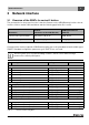

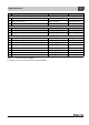

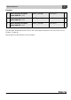
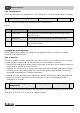

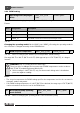
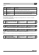
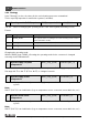
Table Of Contents
- Contents
- 1 Explanation of symbols and safety instructions
- 1.1 Guideline to symbols
- 1.2 Safety instructions
- 2 Product description
- 3 Network interface
- 4 Operating basics
- 5 Incorporation of Logamatic 4000 in LON networks via Logamatic LON-Gateway
- 6 The LON-Gateway as LonMark object
- 7 Error list

Network interface
Technical Information Logamatic LON-Gateway- Subject to modifications resulting from technical improvements!
20
3
3.2.4 Strategy
In the "Strategy" section, the values for the entire heating system are summarized.
This is especially important for multi-boiler systems (cascades).
Format:
Changing the operating mode
With the HVAC_heat / HVAC_off setting, the operating mode for the consumer is changed
externally via the LON data bus.
Set range: 32 °F to 194 °F (0 °C to 90 °C); in 1-degree intervals
Note:
230 °F (110 °C) is an invalid value (e.g. no temperature sensor connected, sensor defective, etc.).
Note:
230 °F (110 °C) is an invalid value (e.g. no temperature sensor connected, sensor defective, etc.).
43 Operating mode (D/N/A) system SNVT_hvac_mode (108) nviAnl_TgNtAt 2
Tab. 29 Value for changing the operating mode of the entire system (all heating zones)
Value Designation Description
0 HVAC_AUTO The system works according to the internal setting on the control
panel (automatic mode).
1 HVAC_heat The system is turned on (all on) and works in manual day mode.
6 HVAC_off The system is turned off (all off).
Tab. 30
44 System supply set point
temperature
SNVT_temp_p(105) nviAnlVorgabe_Tp 2
Tab. 31 Value for changing the system set point temperature (boiler supply temperature)
45 System supply actual
temperature
SNVT_temp_p(105) nvoAnlVLIst_Tp 2
Tab. 32 Display of the currently-measured supply temperature for a floor-standing multi-boiler
system
46 System return actual
temperature
SNVT_temp_p(105) nvoAnlRLIst_Tp 2
Tab. 33 Display of the currently-measured return temperature for a floor-standing multi-boiler
system