
Operating Instructions
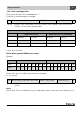
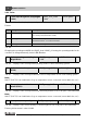
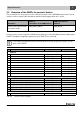
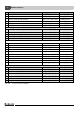
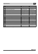

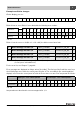
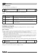
Table Of Contents
- Contents
- 1 Explanation of symbols and safety instructions
- 1.1 Guideline to symbols
- 1.2 Safety instructions
- 2 Product description
- 3 Network interface
- 4 Operating basics
- 5 Incorporation of Logamatic 4000 in LON networks via Logamatic LON-Gateway
- 6 The LON-Gateway as LonMark object
- 7 Error list

Network interface
Technical Information Logamatic LON-Gateway- Subject to modifications resulting from technical improvements!
26
3
3.4 Description of the SNVTs for variant 4 boilers
3.4.1 General
Format: YYYY/MM/DD hh:mm:ss
Note:
230 °F (110 °C) is an invalid value (e.g. no temperature sensor connected, sensor defective, etc.)
For the error list, see Chapter 7, page 43.
The current errors are displayed per control panel. Up to 4 errors that occurred at the same time can
be displayed. If an error has been eliminated, it disappears from the error list. If more than four errors
have occurred, an error not yet eliminated moves up and is displayed.
Error messages are displayed as 2-byte values (2 x 8 bits). The first byte (the first 8 bits seen from
the left) displays errors from the control panel of boiler 2. The second byte (the remaining 8 bits)
displays errors from the control panel of boiler 1.
Errors that occur are to be interpreted as follows:
Errors are displayed as binary values and must be converted to decimal values. By comparing with
the error list (see Chapter 7, page 43), the associated texts are assigned to the error numbers.
0 Time SNVT_time_ stamp(84) nviUhrzeit 7
Tab. 46 Value for comparison of the time in the Buderus control system with the LON network
1 Outdoor temperature SNVT_temp_p(105) nvoAussen_Tp 2
Tab. 47 Display of the current outdoor temperature
2 Error message 1 boiler 1, 2 SNVT_state(83) nvoFehler1_R1_R2 2
3 Error message 2 boiler 1, 2 SNVT_state(83) nvoFehler2_R1_R2 2
4 Error message 3 boiler 1, 2 SNVT_state(83) nvoFehler3_R1_R2 2
5 Error message 4 boiler 1, 2 SNVT_state(83) nvoFehler4_R1_R2 2
Tab. 48 Outputs for error messages 1 (control panel with address 1) and boiler 2 (control panel
with address 2)
First byte - error control panel 2 Second byte - error control panel 1
Display 0000000000000000
Interpretation 2
0
2
1
2
2
2
3
2
4
2
5
2
6
2
7
2
0
2
1
2
2
2
3
2
4
2
5
2
6
2
7
Tab. 49