
Operating Instructions
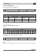
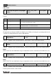
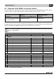
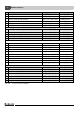

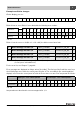
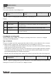
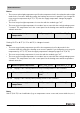
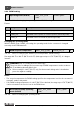
Table Of Contents
- Contents
- 1 Explanation of symbols and safety instructions
- 1.1 Guideline to symbols
- 1.2 Safety instructions
- 2 Product description
- 3 Network interface
- 4 Operating basics
- 5 Incorporation of Logamatic 4000 in LON networks via Logamatic LON-Gateway
- 6 The LON-Gateway as LonMark object
- 7 Error list

Technical Information Logamatic LON-Gateway- Subject to modifications resulting from technical improvements!
27
Network interface
3
Example: nvoFehler changes
On the display, you see:
Boiler 2 has no error. Boiler 1 has a fault with the following error number:
Boiler 1 has the error no. 49 (49 = 1 + 16 + 32), the boiler sensor has a fault
For the error list, see Chapter 7, page 43.
Error messages are displayed as 2-byte values (2 x 8 bits). The first byte (the first 8 bits seen from
the left) displays errors from the control panel of boiler 4. The second byte (the remaining 8 bits)
displays errors from the control panel of boiler 3. Errors that occur are to be interpreted as follows:
Interpretation as described for error messages boiler 1, 2.
nvoFehler1 0 000000010001100
Tab. 50
nvoFehler1 0 000000010001100
Interpretation 2
0
2
1
2
2
2
3
2
4
2
5
2
6
2
7
2
0
2
1
2
2
2
3
2
4
2
5
2
6
2
7
Meaning 1 16 32
Tab. 51
6 Error message 1 boiler 3, 4 SNVT_state(83) nvoFehler1_R3_R4 2
7 Error message 2 boiler 3, 4 SNVT_state(83) nvoFehler2_R3_R4 2
8 Error message 3 boiler 3, 4 SNVT_state(83) nvoFehler3_R3_R4 2
9 Error message 4 boiler 3, 4 SNVT_state(83) nvoFehler4_R3_R4 2
Tab. 52 Outputs for error messages of boiler 3 (control panel with address 3) and boiler 4
(control panel with address 4)
First byte - error control panel 2 Second byte - error control panel 1
Display 0000000000000000
Interpretation 2
0
2
1
2
2
2
3
2
4
2
5
2
6
2
7
2
0
2
1
2
2
2
3
2
4
2
5
2
6
2
7
Tab. 53