
Operating Instructions

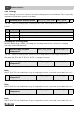

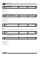


Table Of Contents
- Contents
- 1 Explanation of symbols and safety instructions
- 1.1 Guideline to symbols
- 1.2 Safety instructions
- 2 Product description
- 3 Network interface
- 4 Operating basics
- 5 Incorporation of Logamatic 4000 in LON networks via Logamatic LON-Gateway
- 6 The LON-Gateway as LonMark object
- 7 Error list

Technical Information Logamatic LON-Gateway- Subject to modifications resulting from technical improvements!
33
Network interface
3
3.4.5 Boiler 1
This section describes "boiler 1."
Burner OFF [0 %]
ON [> 0 %]
Current output [%]
Note:
230 °F (110 °C) is an invalid value (e.g. no temperature sensor connected, sensor defective, etc.).
Note:
230 °F (110 °C) is an invalid value (e.g. no temperature sensor connected, sensor defective, etc.).
28 Status burner 4000 boiler 1 SNVT_lev_cont (21) nvoKS1_Br_4000 2
Tab. 73 Indicator for boiler 1 with Logamatic 4000 and third party burner
29 Temperature 4000 boiler 1 (FK)
actual
SNVT_temp_p(105) nvoKS1VLIst_4000 2
Tab. 74 Display of the current boiler temperature for boiler 1 with Logamatic 4000 and third
party burner
30 Additional temperature 4000
boiler 1 (FZ) actual
SNVT_temp_p(105) nvoKS1FZIst_4000 2
Tab. 75 Display of the measured temperature on the additional temperature sensor FZ in the
supply of boiler 1 with Logamatic 4000 and third party burner
31 Boiler hours of operation 4000
boiler 1 level 1
SNVT_time_hour(124) nvoKS1Br4000S1_h 2
Tab. 76 Display of the hours of operation for the level 1 (basic load) of boiler 1 with
Logamatic 4000 and third party burner
32 Boiler hours of operation 4000
boiler 1 level 2
SNVT_time_hour(124) nvoKS1Br4000S2_h 2
Tab. 77 Display of the hours of operation for the level 2 (basic load) of boiler 1 with
Logamatic 4000 and third party burner