
Operating Instructions
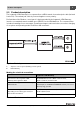
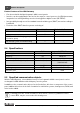
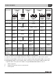
Table Of Contents
- Contents
- 1 Explanation of symbols and safety instructions
- 1.1 Guideline to symbols
- 1.2 Safety instructions
- 2 Product description
- 3 Network interface
- 4 Operating basics
- 5 Incorporation of Logamatic 4000 in LON networks via Logamatic LON-Gateway
- 6 The LON-Gateway as LonMark object
- 7 Error list

Product description
Technical Information Logamatic LON-Gateway- Subject to modifications resulting from technical improvements!
8
2
Product features of the LON-Gateway
• Can be used with all digital Logamatic 4000 control panels
• Interface can be equipped after the fact for the superior control system or for LON thermostats,
integration into existing building control technology/direct digital control (GLT/DDC)
• Interoperability through use of the standard network variable types (SNVT) assured according to
LonMark®
• Provision of the SNVT data for systems consisting of:
2.4 Specifications
2.5 Specified communication objects
With the LON-Gateway, selected data from up to four Logamatic 4000 control panels can be
exchanged via LON data bus with third-party control systems.
In addition to the communication objects for the first boilers, which are a component of the control
panel, additional functions in the form of modules for multi-boiler systems, heating zones, DHW, and
solar can be added.
Communication objects Variant 2 boiler Variant 4 boiler
Boiler 2 4
Heating zones 5 1
DHW zone with tank charging pump and
recirculation pump
11
Solar thermal system for DHW heating 1 -
Tab. 3 Variants
Unit Logamatic LON-Gateway
Power supply L 6 V AC, 400 mA
Frequency Hz 50/60 Hz
Power consumption VA 1.5
Dimensions (width/height/depth) inches (mm) 5-1/8" / 5-1/2" / 9/16"
(130/140/40)
Weight oz (g) 14 (400)
Operating temperature °F (°C) 40 to 122 (5 to 50)
Protection level IP40
Tab. 4 Specifications
If heating zones are served via LON, no other remote controls, e.g. Buderus remote
control BFU, may be connected to this heating zone.