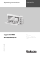
Operating instructions 6 720 618 477-00.1RS Room controller For users RC35 programming unit Read carefully before use.
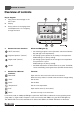
Overview of controls Overview of controls Key to diagram: 1 Flap; pull the recessed grip on the left to open 2 Display 3 Rotary selector for changing values and temperatures or for navigating through the menus 4 Buttons for basic functions: When the LED lights up, “AUT” (automatic) • the switching program is active (automatic switchover between day and night room temperatures). “Daytime operation” (manual) • the heating system operates at the set day room temperature.
Contents Contents Overview of controls . . . . . . . . . . . . . . . . . . . . . . . . . . . . . . . . . . . . . . . . . . . . . . . . . . . . . . . 2 Guide to instructions . . . . . . . . . . . . . . . . . . . . . . . . . . . . . . . . . . . . . . . . . . . . . . . . . . . . . . . 5 1 Explanation of symbols and safety instructions . . . . . . . . . . . . . . . . . . . . . . . . . . . . . . . 6 1.1 Explanation of symbols . . . . . . . . . . . . . . . . . . . . . . . . . . . . . . . . . . . . . . . . . . .
Contents 5.5.1 Operating modes for RC35 heating circuits . . . . . . . . . . . . . . . . . . . . . . . . . . . . . . . . . . 5.5.2 Operating modes for DHW . . . . . . . . . . . . . . . . . . . . . . . . . . . . . . . . . . . . . . . . . . . . . . . . 5.5.3 Operating modes for DHW circulation . . . . . . . . . . . . . . . . . . . . . . . . . . . . . . . . . . . . . . . 5.5.4 Operating modes for solar . . . . . . . . . . . . . . . . . . . . . . . . . . . . . . . . . . . . . . . . . . . . . . . . . 5.
Guide to instructions Guide to instructions These operating instructions contain all information on the function and operation of the Logamatic RC35 programming unit. Introduction to the user menu Chapter 5.1 explains in detail the steps needed for programming all the settings in the user menu. The operation is only briefly dealt with in the following sections. Display texts Words appearing on the display are shown in bold in flowing text.
Explanation of symbols and safety instructions 1 1 Explanation of symbols and safety instructions 1.1 Explanation of symbols Warning symbols Safety instructions in this document are framed and identified by a warning triangle which is printed on a grey background. Electrical hazards are identified by a lightning symbol surrounded by a warning triangle. Signal words indicate the seriousness of the hazard in terms of the consequences of not following the safety instructions.
Explanation of symbols and safety instructions 1 1.2 Safety instructions Installation and commissioning B Observe these instructions to ensure satisfactory operation. B The appliance must only be installed and commissioned by an authorised installer. Risk of damage due to operator error Operator errors can lead to injuries and/or material losses. B Ensure that children never operate this appliance unsupervised or play with it.
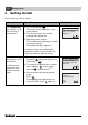
2 2 Getting started Getting started Initial situation: the flap is closed. What do I do ... Operation Display/result if it is temporarily too cool/warm in the entire home on a particular day? B Turn rotary selector . The current room temperature setting starts flashing. B Turn the rotary selector to set the required room temperature. B Release the rotary selector. The modified room temperature is saved (and stops flashing). The standard display reappears.
Getting started 2 What do I do ... Operation for one-off heating outside the usual times (outside the switching program)? B Activate manual day mode: press The LED next to lights up. → manual day mode (“continuous heating”); automatic mode is switched off to save energy during long absences? → manual night mode (“permanently reduced”); automatic mode is switched off Tab. 2 Display/result . You have selected daytime operation.
2 Getting started What do I do ... Operation Display/result to save energy when on holiday? B Set holiday mode in the user menu (Æ page 40). to change the holiday temperature? Requirement: holiday mode is active. B Turn rotary selector . The room temperature is changed for the rest of the holiday period. in summer (DHW only, no central heating)? The programming unit switches automatically between summer mode and winter mode, triggered by temperature.
Information about the appliance 3 3 Information about the appliance 3.1 Product description The RC35 programming unit makes it easy to operate your Buderus heating system. You can set the room temperature for your entire home using the rotary selector. You only need to adjust the thermostatic valves on the radiators if it is too cool or too warm in individual rooms.
4 4 Principles of operation Principles of operation 4.1 Display The following elements appear on the display of the RC35 programming unit during standard operation: 1 4 2 2 3 6 720 618 414-01.1RS Fig.
Principles of operation 4 4.3 Setting the operating mode You can activate the operating mode directly by pressing the button shown. Operating mode automatic operation (recommended setting) Button Meaning The switching program is active. The system will switch over automatically between day mode and night mode at a set time (switching point).1) At night the heating system will operate with a reduced room temperature (factory setting; night shutdown is also possible).
4 Principles of operation 4.4 Changing the room temperature temporarily Follow this procedure if you only want to change the room temperature up until the next switching point. At the switching point, the system switches over automatically between day and night modes (Æ page 31). The heating system will then go back to the standard room temperature setting. Initial situation: the flap is closed. Operation 1. Turn rotary selector Result . The current room temperature setting starts flashing.
Principles of operation 4 4.5 Changing the room temperature permanently NOTICE: System damage due to frost! If room temperatures are set below 10 °C, rooms may cool down so much that pipes in external walls (for example) may freeze in cold weather. B Set room temperatures higher than 10 °C. Operation Result 1. To change the day room temperature: hold down simultaneously turn rotary selector . 2. Changing the night room temperature1): hold down turn rotary selector at the same time. 3.
4 Principles of operation 4.6 Setting the room temperature for particular heating circuits If the heating system comprises several heating circuits (Æ page 27), you can adjust the room temperature for selected heating circuits with . Only heating circuits that are not equipped with an RC2x remote control unit will be displayed. No selection is possible if there is only one heating circuit. All RC35 heat. circuits have the same room temperature set values.
Principles of operation 4 4.7 Setting the date and time Your heating system requires the date and time to operate correctly. The clock keeps running for about 8 hours in the event of a power failure. If a power failure lasts longer than that, the display will indicate that you need to reset the date and time. Setting the date: 1. Open the flap (by pulling the recessed grip on the left). 2. Press . The year starts flashing. 3. To set the year: hold down and turn the rotary selector at the same time. 4.
4 Principles of operation 4.8 Setting DHW functions Risk of scalding from DHW temperatures over 60 °C! WARNING: Risk of scalding! The factory setting for the DHW temperature is 60 °C. There is a risk of scalding at the hot water draw-off points if the temperature is set higher than this and also following thermal disinfection. B If the temperature set is higher than 60 °C or following thermal disinfection: never open any hot water tap without mixing in cold water as well.
Principles of operation 4 What is it for? Operation Heating up DHW regularly If you regularly need large amounts of hot water outside the set times for day mode, you can set a separate program for DHW (Æ page 38). Switching thermal disinfection on/off B Set thermal disinfection (Æ page 44). This function heats up the DHW to a temperature sufficient to kill pathogens (e.g. legionella). Tab. 7 Setting DHW functions 1) Setting subject to the boiler installed.
4 Principles of operation 4.9 Viewing information (Info menu) You can use the INFO menu to view set and recorded values. The exact information available depends on the components installed in your heating system. Operation 1. Result Open the flap (by pulling the recessed grip on the left). Fr 02.12.2005 10:20h 21.5°C 2. Press to open the INFO menu. The message on the right is displayed for five seconds. It then moves on automatically. By turning the dial you can obtain plant information.
Principles of operation 4 Graph displays in the INFO menu (outside temperature variation and solar gain) The INFO menu gives you the option of, for example, viewing graphs showing the variation in outside temperature over the past two days and (if solar components are installed) the solar gain. This way you have a clear overview allowing easy comparison of the relevant values. The graphs in both displays are updated every 15 minutes and a new graph is started at 00:00 h (midnight).
4 Principles of operation Saving data If the power supply is interrupted, the RC35 programming unit saves the solar gain data for as long as the time buffer lasts. If the interruption lasts longer, the recordings are reset to zero and start again. The same applies if the date in the RC35 is changed. If the time is changed, the graphic display is set to zero and the data recorded in the table for the week is retained.
Operation with the user menu 5 5 Operation with the user menu 5.1 Introduction to the user menu The user menu allows you to make specific settings. The procedure for operation is always the same: 1. 2. 3. 4. 5. Open the flap (by pulling the recessed grip on the left). Press to open the USER MENU. Turn rotary selector to change the selection. Press to make your selection. To change the value, hold down (the value starts flashing) and turn rotary selector same time. Release . The modified value is saved.
5 Operation with the user menu Operation 4. Press Result to confirm the selection. The USER\OPERATING MODE menu is opened. The appearance of the display depends on the number of heating circuits. If there is only one heating circuit installed with no DHW and no DHW circulation pump, this screen will not appear at all (Æ page 26). USER\OPERATING MODE heating circuit 1 heating circuit 2 heating circuit 3 domestic hot water Continue to the next step. 5. Press to select heating circuit 1.
Operation with the user menu 5 Operation 9. Press Result to go back one step. -orTo finish making settings: press the flap. several times or close The standard display reappears. You can enter all settings in the USER MENU using this procedure. Tab. 8 How to use the user menu (example) 5.
5 Operation with the user menu 5.3 Selecting a heating circuit If your heating system is equipped with more than one heating circuit: prior to making some adjustments, you will need to select the heating circuits(s) to which the settings should apply. Only the heating circuits that are actually installed will be displayed: Heating circuit selection Meaning heating circuit 1 Heating circuit without mixing valve From heating circuit 21) Heating circuits with mixing valve, i.e.
Operation with the user menu 5 What is a heating circuit? A heating circuit describes the circuit taken by the heating water from the boiler via the radiators and back again. Multiple heating circuits can be connected to one boiler; for example, one heating circuit for radiators and another heating circuit for underfloor heating. The radiators are supplied with a higher flow temperature than the underfloor heating system.
5 Operation with the user menu Designations of the heating circuits in the example in Fig. 2 When you make adjustments to a particular heating circuit, first select the appropriate heating circuit. A list of designations as shown in Tab. 11 is available for selection. Different temperatures for the heating circuits (Æ Tab. 11, [1] b) can also be entered using the RC35 programming unit without a remote control, if your heating contractor has made corresponding settings.
Operation with the user menu 5 5.4 Selecting the standard display This menu item can be used to select the default value to be displayed in the upper row of the display screen (permanent display). 1. Open the user menu. 2. Select standard display.
5 Operation with the user menu 5.5.2 Operating modes for DHW You can set one of the following operating modes for DHW heating: • automatic operation (switching program). This can be either the switching program for central heating or a specific DHW program (Æ page 38). • permanently ON (manual continuous mode). The DHW is permanently maintained at the set temperature. • permanently OFF/ECO (manual night mode). You can use to start DHW heating when needed (“Heating up DHW once”, Æ page 18). 5.5.
Operation with the user menu 5 5.6 Setting the switching program Automatic mode ensures automatic changeover between day and night mode at defined times. The factory settings means 21 °C or 17 °C are set for day or night mode. Before you select a switching program (i.e.
5 Operation with the user menu 5.6.1 Selecting a program Here you can select and activate a switching program. This can be one of the preset standard programs (Æ Tab. 12, page 33) or one created or modified by you. You can save and later select two new or modified switching programs as user defined 1 or user defined 2. Selecting a preset switching program: 1. Hold down and turn the rotary selector to select and activate a switching program. 2. Press to return to the list of options. 3.
Operation with the user menu 5 Start and stop points in the standard programs Program Day ON OFF family Mon–Thu 5:30 22:00 (factory setting) ON OFF Fri 5:30 23:00 Sat 6:30 23:30 Sun 7:00 22:00 early morning Mon–Thu 4:30 22:00 (early shift work) Fri 4:30 23:00 Sat 6:30 23:30 Sun 7:00 22:00 evening Mon–Fri 6:30 23:00 (late shift work) Sat 6:30 23:30 Sun 7:00 23:00 morning Mon–Thu 5:30 8:30 12:00 22:00 (part-time work, Fri 5:30 8:30 12:00 23:00 morning
5 Operation with the user menu 5.6.2 Viewing the current program You can use display curr. prog. to view the currently set switching program in the form of a graph (Æ Fig. 3). • The graph always shows the switching program for one day or a block of days. • The current switching point will flash (circle and cross alternately). Below the graph, you can see the time for that switching point and the temperature that applies from that time onwards. • Other switching points are marked with a cross. Fig.
Operation with the user menu 5 4. Repeat steps 1 to 3 to change other switching points. 5. Press when you have finished making entries. If you have changed the program and then do not press any button for five minutes, the system assumes you have finished making entries and goes on to the next step. 6. Hold down and turn the rotary selector, to save the modified program as user defined1 or user defined2. The selected program, user defined1 or user defined2, is used from now on for that heating circuit. 7.
5 Operation with the user menu If you have changed the program and then do not press any button for five minutes, the system assumes you have finished making entries and goes on to the next step. 7. Hold down and turn the rotary selector to save the modified or new program as user defined1 or user defined2. The selected program, user defined1 or user defined2, is used from now on for that heating circuit. 8. Select do not save to cancel. 5.6.
Operation with the user menu 5 5.6.6 Setting room temperatures The room temperatures menu item is only available for heating circuits without a remote control unit (the first case below). In the other two cases, the room temperatures menu item is not displayed. Possible case scenarios: • Heating circuits without remote control (Æ page 53, setting “none”): different room temperatures are possible for each circuit, in contrast to the RC35 heating circuits. The room temperature is set as described below.
5 Operation with the user menu 5.7 Setting a DHW program With the setting by heating circuit (factory setting), the start and stop times for DHW heating follow those of the selected switching program. This ensures that DHW is available during the heating phases (day mode).
Operation with the user menu 5 5.9 Setting the switchover threshold for summer/winter mode Requirements: an outside temperature sensor must be fitted. The heating system is controlled by the outside temperature (with or without influence of room temperature Æ page 46). In the case of room temperature control, the sum./win. threshold menu item is not displayed. When the outside temperature falls below an adjustable threshold, the heating system automatically switches over to winter mode (heating on).
5 Operation with the user menu Should the official details for the changeover change, adjust the summer/wintertime changeover to no. B Change the time manually. 5.11 Setting the DHW temperature The DHW temperature is the temperature to which the water in the DHW cylinder is heated.1) WARNING: Risk of scalding! The factory setting for the DHW temperature is 60 °C. There is a risk of scalding at the draw-off points if the temperature is set higher than this.
Operation with the user menu 5 – Individual heating circuits: only heating circuits which are not assigned to the RC35 will be displayed; in other words, those which have their own remote control unit or which have no remote control unit. 4. Setting at home or away from home (absent): – absent: heating is operated at a reduced, adjustable holiday temperature (reduced mode). If “complete system” was previously selected, DHW and DHW circulation are switched off.
5 Operation with the user menu Domestic hot water (DHW) Holiday set as absent: complete system absent: individual heating circuits at home: complete system at home: individual heating circuits DHW program as for heating circuits (factory setting) Holiday mode (DHW off/ ECO) With all HC in holiday mode: holiday mode (DHW off/ ECO) If at least one HC not set to holiday: no holiday mode3) As per Saturday switching program If all HC set to holiday: same as switching program for Saturdays3) If at least one
Operation with the user menu 5 5.13 Setting the party function You can use the party function (extension of period of use) to postpone the time when your heating system normally switches to night mode (as defined in the switching program) to a later time. This means your home will be heated for longer in day mode (continuous heating) if you want to stay up later than usual in the evening. 1. Open the user menu. 2. Select party function. 3.
5 Operation with the user menu Instead of making the setting via the user menu, you can use the following shortcut: B Press and hold down . B Open flap. B Turn rotary selector at the same time to set the number of hours (0 to 99). 5.15 Setting thermal disinfection If this function1) is activated, DHW is heated once a week or once a day to a temperature sufficient to kill pathogens (e.g. legionella).
Operation with the user menu 5 A thermometer may indicate temperature fluctuations more slowly or rapidly than the programming unit. B Therefore, never calibrate the programming unit during phases when your heating system is cooling down or heating up. 1. Open the user menu. 2. Select the room temp. correct. option. 3. Setting the Calibration of the room temperature: the “K” on the display stands for the unit Kelvin; 1 K corresponds to 1 °C. The factory setting is 0.0 K.
6 6 Information on setting the programming unit Information on setting the programming unit 6.1 Control modes for heating control The heating control can operate in three control modes: Upon request, your heating contractor will select and set up one of these options: • Outside temperature control (weather-compensated control): the outside temperature is recorded by means of a temperature sensor.
Information on setting the programming unit 6 6.2 Tips for energy efficiency • You can save around 6 % on your heating costs by reducing the daytime room temperature by 1 °C. • Only heat if you need warmth. Use the switching programs for automatic night setback. • Air your home wisely: leave the windows wide open for a few minutes rather than leaving them slightly open all the time. • Close the thermostatic valves whilst airing heated rooms.
7 7 Troubleshooting Troubleshooting This chapter deals with frequently asked questions about your heating system. This will in many cases enable you to eliminate suspected faults. At the end of the chapter you will find a table listing faults and corresponding remedies. 7.
Troubleshooting 7 Why does the pump run at night, even though the home is not being heated at all or only very little? This depends on the setting chosen by your heating contractor for night setback. • reduced operation: Even when the home is only being heated a little, the pump runs to achieve the set room temperature, even if low. • shut-down mode: the heating system (and therefore also the pump) is automatically shut down in night mode.
7 Troubleshooting 7.2 Fault messages and service messages The RC35 programming unit differentiates between three types of messages: • Faults (in boiler operation) • Plant errors (incorrect settings on the programming unit, or component malfunctions) • Service messages (indicating that some servicing is required) Faults The display shows the following message: Your system has a malfunction. Please open the cover of the operating unit.
Troubleshooting 7 Plant errors and service messages The display shows please open cover in the bottom row on the display. The heating system stays operational for as long as possible; in other words, central heating can continue. 1. Open the flap (by pulling the recessed grip on the left). 2. Turn rotary selector . The display indicates whether there is a fault message (= plant error) or a servicing message.
7 Code Hxx H07 Troubleshooting Display Cause please open cover Maintenance is required. Remedy B Make arrangements to have the system serviced by your heating contractor. The heating system remains operational for as long as possible. Water pressure too The water pressure in the This is the only service message low. heating system has dropped to (H07) that you can remedy a low level. yourself.
Setup report 8 8 Setup report The setup report is to be completed by your heating contractor during commissioning and is for your information. Allocation of heating circuits: Area of dwelling (examples: ground floor, granny flat) Remote control (RC35, RC2x, RC20/RF, none1)) Heating circuit 1 Heating circuit 22) Heating circuit 32) Heating circuit 42) Tab.
8 Setup report Important settings for your heating system: Setting options Reduction mode (night setback) Outdoor setback mode, Room setback mode, shut-down mode, reduced operation Control function (Æ page 46) Outside temperature control (with/ without room influence), room temp. controlled Htg. charact. curve Design temperature: Minimum outside temperature: Offset: Type of building light, medium, heavy DHW circulation pump runtime1) durat.
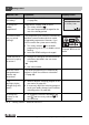
Logamatic EMS RC35 programming unit - Subject to technical modifications Push & turn to set parameter. room standard display operation modes switching programme sum./win. threshold summer / winter DHW temperature holiday party function pause function therm. disinfection room temp. correct. Calibration of the room temperature: USER\ROOM TEMPERATURE PARTY FCT\PAUSE FCT HC For how many hours do you want to set party/pause? heating circuit 1 heating circuit 3 RC35 heat.
Index Index A H Automatic mode . . . . . . . . . . . . . . . . . . . . 13, 29 Away from home. . . . . . . . . . . . . . . . . . . . . . 8–9 Heat pump . . . . . . . . . . . . . . . . . . . . . . . . . . . 45 Heat pump with gas booster heater . . . . . . 45 Heating circuit - designations in list of options for selection . . . . . . . . . . . . . . . . . . . . . . . . . . . 28 - explanation . . . . . . . . . . . . . . . . . . . . . . . . 27 Heating circuit, selecting . . . . . . . . . . . .
Index Preheating phase, heat pump with gas booster heater . . . . . . . . . . . . . . . . . . . . . . . . . 45 Pump . . . . . . . . . . . . . . . . . . . . . . . . . . . . . . . . 49 R RC35 heating circuits. . . . . . . . . . . . . . . 26–28 Reduced operation . . . . . . . . . . . . . . . . . . . . . 49 Reference room. . . . . . . . . . . . . . . . . . . . . . . . 46 Remote control . . . . . . . . . . . . . . . . . . . . . . . . 27 Reset . . . . . . . . . . . . . . . . . . . . . . . . . . . . . . . .
Notes 58 Logamatic EMS RC35 programming unit - Subject to technical modifications
Notes Logamatic EMS RC35 programming unit - Subject to technical modifications 59
Buderus Cotswold Way, Warndon, Worcester WR4 9SW Customer service: 0844 892 3004 Technical support: 0844 892 4224 Fax: 01905 753130 www.buderus-commercial.co.uk In the UK and IE, Buderus is a brand name of Bosch Thermotechnology Ltd.