User Manual WHR-HP-GN AirStation Wireless N Technology HighPower Router, Access point & Bridge Ò ×Å ÐÏ Ù ÒÉÔ ÃÕ ÓÅ ÓÓ ÌÅ ÉÒÅ ×Å ÅÒ ÕÔ ÒÏ Ç ÄÉÁ www.buffalotech.com 35010924 ver.01 v1.
Contents Chapter 1 Product Overview.................................................. 5 Features.................................................................................................................. 5 Air Navigator CD Requirements.................................................................... 6 150 Mbps High Speed Mode.......................................................................... 6 Package Contents..................................................................................
Internet (Router Mode only)....................................................................................25 PPPoE (Router Mode only)........................................................................................26 DDNS (Router Mode only)........................................................................................29 LAN....................................................................................................................................31 DHCP Lease (Router Mode only)..
Diagnostic............................................................................................................. 65 System Info.....................................................................................................................65 Log....................................................................................................................................67 Packet Info.............................................................................................................
Appendix C TCP/IP Settings in Windows................................ 89 Windows Vista...................................................................................................... 89 Windows XP.......................................................................................................... 90 Appendix D Restoring the Default Configuration................ 91 Appendix E Regulatory Compliance Information................. 92 Federal Communication Commission Interference Statement.............
Chapter 1 Product Overview Features Supports Draft IEEE802.11n and IEEE802.11b/g With support for current Wireless-N, Wireless-G, and Wireless-B standards, the AirStation can transfer data to and from all standard 2.4 GHz wireless clients. Dual speed mode Dual speed mode makes wireless transmission faster by using 2 channels, allowing 300 Mbps data transmission. Support AOSS and WPS Both AOSS (AirStation One-touch Secure System) and WPS (Wi-Fi Protected Setup) are supported.
Chapter 1 Product Overview Initialization To restore settings back to the factory defaults, hold down the Reset button on the bottom of the unit. Browser Based Administration This unit can be easily configured from a web browser on your computer. Auto Mode (Router/Bridge Automatic Recognition) Auto mode detects whether your network has a router or not and automatically switches to the appropriate router or bridge mode. You can also manually switch between modes. (See page 10).
Chapter 1 Product Overview Package Contents Following items are included in your AirStation. If any of the items are missing, please contact your vender. • WHR-HP-GN.................................................................................................................................... 1 • AC adapter....................................................................................................................................... 1 • Stand for vertical/wall-mounting...........................
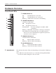
Chapter 1 Product Overview Hardware Overview Front Panel LED's 1 POWER LED (Green) On: The AC adapter is connected Off: The AC adapter is not connected Blinking: An Ethernet connection is transmitting 2 SECURITY LED (Amber) Indicates security status. 1 2 3 Off: Encryption is not set On: Encryption has been set Double blink: The unit is waiting for an AOSS or WPS security key Blinking: AOSS/WPS error; failed to exchange security keys.
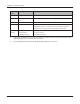
Chapter 1 Product Overview Diag LED status Meaning Status 2 blinks *1 Flash ROM error Cannot read or write to the flash memory. 3 blinks * Ethernet (wired) LAN error Ethernet LAN controller is malfunctioning. 4 blinks *1 Wireless LAN error Wireless LAN controller is malfunctioning. 5 blinks IP address setting error Because the network addresses of both the Ineternet port (WAN port) and the LAN port are the same, it is not possible to establish communication.
Chapter 1 Product Overview Back Panel 6 6 On: Off: Auto: ÒÏÕÔÅÒ ÏÎ ÏÆÆ ÁÕÔÏ ÌÁÎ ᴮ ᴯ 7 8 ᴱ POWER LED (Green) On: An Ethernet device is connected. Flashing: An Ethernet device is communicating. 8 LAN Port Connect your computer, hub, or other Ethernet devices to these ports. This switching hub supports 10Mb/s and 100Mb/s connections. 9 INTERNET LED (Green) On: The Internet port is connected. Flashing: The Internet port is transmitting data.
Chapter 1 Product Overview Top 12 12 AOSS Button Hold down this button until the Security LED flashes (about 1 second), while the unit's power is on, initiates AOSS/WPS mode, allowing the unit to exchange security keys with AOSS or WPS compatible devices. Bottom ᵏᵂᵐᵂᵑ 13 13 RESET Button WHR-HP-GN User Manual Holding this button until the Diag LED comes on, while the unit's power is on, will initialize its settings.
Chapter 1 Product Overview Right Side 14 14 Factory Default Settings WHR-HP-GN User Manual This sticker shows the AirStation’s MAC address (SSID), WPS PIN, and default encryption key.
Chapter 2 Placing Your AirStation Vertical Placement To place unit vertically, refer to the following figure to place the vertical/wall-mounting stand. 1 1 2 Horizontal Placement Place the unit horizontally as the figure below.
Chapter 2 Placing Your AirStation Wall-Mounting 1 Fix the vertical/wall-mount stand on the wall using screws. 8.5 cm (~3.3 inches) 2 WHR-HP-GN User Manual Match the centers of your AirStation and its vertical/wall-mounting stand, and slide downward as shown on the left.
Chapter 3 Installation CD Setup You can set up this unit with the included software CD. Insert the CD into your PC and follow the instructions on the screen. * CD Setup is supported for Windows Vista/XP only. Manual Setup To configure your AirStation manually, follow the procedure below. 1 Turn off your computer and modem. 2 1) turn off the computer 2) disconnect 2) disconnect ÏÆÆ modem Unplug the LAN cable which connects your computer and modem.
Chapter 3 Installation 5 Connect you computer to one of the AirStation’s LAN ports with the LAN cable. Wireless Router ᴥrear sideᴦ ÒÏÕÔÅÒ ÏÎ ÏÆÆ ÁÕÔÏ ÌÁÎ ᴮ 2) connect ᴯ ᴰ 1) connect ÏÆÆ ᴱ computer ÉÎÔÅÒÎÅÔ LAN cable ÐÏ×ÅÒ 6 Turn on the AirStation, wait one minute, and then turn on your computer.
Chapter 4 Configuration This chapter explains the advanced settings for the AirStation. To change advanced settings, use the AirStation's web-based configuration utility. How to Access the Web-Based Configuration Utility To display the configuration of the AirStation, follow the procedure below. 1 Launch a web browser. 2 Enter the router’s LAN-side IP address in the address field, and press the "Enter" key.
Chapter 4 Configuration 4 The configuration screen is displayed. Help is always displayed on the right side of the configuration screen. Refer to the Help screens for more information on each page in the web-based configuration screens.
Chapter 4 Configuration Configuration Menu (Router Mode) The menu structure for the AirStation in router mode is the following. Please refer to the pages listed at right for explanations of each item.
Chapter 4 Configuration DMZ Configure a DMZ for services with external users, secure from normal LAN operations. Page 53 UPnP Configure UPnP (Universal Plug and Play). Page 54 QoS Configure priority for packets that require a certain data flow. Page 55 Name Configure the AirStation’s NetBIOS name . Page 56 Password Configure the AirStation’s login password for access to configuration screens. Page 57 Time/Date Configure the AirStation’s internal clock.
Chapter 4 Configuration Configuration Menu (Bridge Mode) The menu structure during a bridge mode is the following. Please refer to respective page for explanations regarding to each item.
Chapter 4 Configuration Packet Info View all packets transferred by the AirStation. Page 68 Client Monitor View all devices currently connected to the AirStation. Page 69 Ping Test the AirStation’s connection to other devices on the network. Page 70 Logout Click this to log out of the AirStation’s configuration screens.
Chapter 4 Configuration Setup The home page of the configuration screen. You can verify settings and the status of the AirStation here. Parameter Meaning Internet/LAN (LAN Config) Displays the configuration screen for the Internet port and LAN ports. Wireless Config Click this button to display the configuration screen for wireless settings. Security Click this button to display the configuration screen for security.
Chapter 4 Configuration Parameter Meaning Admin Config Click this button to display the configuration screen which is related to the administration of the AirStation. Diagnostic Click this button to display the status of the AirStation. Easy Setup Enable you to configure the AirStation easily such as an encryption method of the wireless signal or changing a wireless channel. Internet Information Displays the current information where the AirStation is connected on the Internet side.
Chapter 4 Configuration Internet/LAN (LAN Config) Internet (Router Mode only) The screen to configure a port of the Internet side. Parameter Meaning Method of Acquiring IP Address Specify how the Internet side IP address is obtained. Default Gateway Configure an IP address for the default gateway. Address of DNS Name Server Specify an IP address of the DNS server. Internet MAC Address Configure the Internet side MAC address.
Chapter 4 Configuration PPPoE (Router Mode only) The screen to configure PPPoE settings. Parameter Meaning Default PPPoE Connection If you have registered multiple connection destinations in PPPoE Connection List, connection destination selected here have priority. You need to configure the route to which PPPoE is connected to if you don’t use the default setting.
Chapter 4 Configuration Parameter Meaning PPPoE Connection No.*-Add This is displayed when clicking “Edit Connection List”. Name of Connection Enter the name to identify the connected destination. You may enter up to 32 alphanumerical characters and symbols. User Name Set the user name which is specified by your provider, used for a PPPoE certification. You may enter up to 32 alphanumerical characters and symbols. Password Set the password specified by your provider for PPPoE certification.
Chapter 4 Configuration Parameter Meaning PPPoE Connection No. *-Add Keep Alive When enabling Keep Alive, the AirStation issues LCP echo request in order to maintain the connection with the PPPoE server once a minute. If the server does not respond more than 6 minutes the line is recognized as disconnected and the AirStation will terminate the connection. If a PPPoE connection is often disconnected, the server may not reply to Keep Alive. Set this to "Disable.
Chapter 4 Configuration DDNS (Router Mode only) The screen to configure Dynamic DNS settings. Parameter Meaning Dynamic DNS Service Select a provider (DynDNS or TZO) for Dynamic DNS. User Name Enter the user name which is registered to the Dynamic DNS service. You may enter up to 64 alphanumerical characters and symbols.
Chapter 4 Configuration Parameter Meaning Domain Name Enter the domain name which is registered to the Dynamic DNS service. You may enter up to 255 alphanumerical characters, hyphens, and periods. * Only when selecting TZO IP Address Update Period Specifies the period to notify the dynamic DNS service provider of the current IP address. When DynDNS is selected, set it between 0 and 35 days. When TZO is selected, set it between 0 and 99 days. If 0 (zero) day is set, no periodic update is performed.
Chapter 4 Configuration LAN The screen to configure a port of the LAN side. Parameter Meaning LAN Side IP Address Set a LAN side IP address and subnet mask. DHCP Server Function Enable or disable the DHCP server, which assigns IP addresses automatically.
Chapter 4 Configuration Parameter Meaning Default Gateway Set the default gateway IP address for the DHCP server to issue to clients. * Router Mode only DNS Servers * Router Mode only WINS Server * Router Mode only Domain Name Set the dDNS server IP address for the DHCP server to issue to clients. Set the WINS server IP address for the DHCP server to issue to clients. * Router Mode only Set the domain name for the DHCP server to issue to clients.
Chapter 4 Configuration DHCP Lease (Router Mode only) The screen to configure DHCP lease. Parameter Meaning IP Address Enter an IP address to lease manually. The IP address should be from the same subnet as the DHCP scope, but not be within the range that DHCP is assigning to other devices. MAC Address Enter the MAC address which identifies the client. Current DHCP Client Information Displays information for current leases.
Chapter 4 Configuration NAT (Router Mode only) The screen to configure settings relating to the network address translation function which is used to connect the LAN side to the Internet. Parameter Meaning Address Translation Enable to use Network Address Translation. Log Output of Deleted Packets Enable to log deleted packets (such as errors) during address translation.
Chapter 4 Configuration Route The screen to configure the communication IP route that the AirStation uses. Parameter Meaning Destination Address Adds a destination IP address and subnet mask to a routing table. Gateway Adds a gateway address to a routing table. Metric The metric is the maximum number of router hops a packet may take on the way to its destination address. Values between 1 and 15 may be entered. The default value is 15.
Chapter 4 Configuration Wireless Config WPS The screen to see the detailed settings and status of WPS. Parameter Meaning WPS Enable to use WPS automatic configuration. External Registrar Enable to accept the external configure requests from other WPS devices. Note: External configure requests will not be accepted if AOSS is in use. AirStation PIN Displays the PIN code of the AirStation. Clicking “Generate PIN” will generate a new PIN code.
Chapter 4 Configuration AOSS The screen to see the detailed settings and status of AOSS.
Chapter 4 Configuration Parameter Meaning Initiates AOSS automatic wireless configuration. Click this, then press or click the AOSS button on your AOSS-compatible wireless client. Repeat for additional AOSS clients. Click this button to disconnect AOSS connections. Note: If AOSS connections are disconnected, the SSID and encryption keys will be restored to their most recent settings before using AOSS.
Chapter 4 Configuration Basic The screen to configure a basic wireless settings. Parameter Meaning Wireless Radio Determines whether to allow wireless communication. If this is unchecked, then no wireless connections will be allowed. Wireless Channel Sets a channel (a range of frequencies) used for wireless connections. Available range of the channel is 1 to 11. With Auto Channel selected, the AirStation will automatically use the best available channel.
Chapter 4 Configuration Parameter Meaning Broadcast SSID If “Allow” is checked, then the AirStation will respond to SSID searches from wireless devices by broadcasting its SSID. If “Allow” is unchecked, then the AirStation ignore SSID searches from wireless devices. [Use Multi Security function] [Do not use Multi Security function] Clicking "Use Multi Security function" will enable the Multi Security function, allowing the use of multiple SSIDs, each with different wireless security settings.
Chapter 4 Configuration Parameter Meaning Wireless encryption Select a type of data encryption for wireless communication from the following options: No encryption Data is transmitted without encryption. Avoid this option since any communication may be intercepted. “No encryption” can be selected only when “No authentication” is selected for Wireless authentication. WEP WEP is a common encryption method supported by most devices. Use an encryption key to communicate with a wireless device.
Chapter 4 Configuration Parameter Meaning Setup WEP encryption key Enter an encryption key to encrypt wireless data. * Use 5 or 13 alphanumeric characters (case-sensitive) for an encryption key when you select character type as the input method. Enter 10 or 26 digits using 0 to 9 and a to f (not case-sensitive) when you select hexadecimal type as the input method.