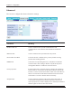
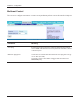
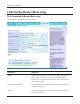
Chapter 4 Configuration Advanced The screen to configure the advanced wireless settings. Parameter Meaning BSS Basic Rate Set Set the communication speeds of administrative and communication control frames of the AirStation and wireless devices. Multicast Rate Set the communication speed of multi-cast packets. Reverse Direction Grant For faster wireless communication, you may enable receiving packets while sending packets.
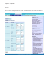
Chapter 4 Configuration WMM The screen to set the priorities for specific communications the AirStation performs.
Chapter 4 Configuration Parameter Meaning WMM WMM is a standard that includes basic Quality of Service (QoS) features for wireless networks. If disabled, QoS features will not be available. WMM-EDCA Parameters You don't usually need to change these settings. Using the default settings is recommended. Priority The following priorities may be applied to individual transmission packets: (Highest) 8, (High) 4, (Normal) 2, and (Low) 1. From the queue, these packets are processed in order of priority.
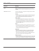
Chapter 4 Configuration MAC Filter The screen to configure the access restrictions from wireless devices. Parameter Meaning Enforce MAC Filtering Enable to restrict wireless connections to devices with registered MAC addresses. Registration List Displays the MAC addresses of registered devices which are permitted to connect wirelessly. [Edit Registration List] Click this button to add a MAC address of a wireless device to the list of permitted devices.
Chapter 4 Configuration Multicast Control The screen to configure restrictions on unnecessary multicast packets sent to the wireless LAN port. Parameter Meaning Snooping If enabled, snooping supervises multicast administrative packets such as IGMP and restricts unnecessary multicast transfers to wired or wireless ports. Multicast Aging Time Set the time to hold the data from multicast snooping in the range of 1 to 3600 (seconds).
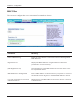
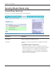
Chapter 4 Configuration Security (Router Mode only) Firewall (Router Mode only) The screen to configure firewall features of the AirStation. Parameter Meaning Log Output Enable to output a log of firewall activity. Basic Rules Enable to use any of the quick filters. Preconfigured quick filters include: Prohibit NBT and Microsoft-DS Routing When this is enabled, you cannot use the Microsoft network feature from the Internet side to the LAN side and from the LAN side to the Internet.
Chapter 4 Configuration Parameter Meaning Reject IDENT Requests Enabling this option will answer IDENT requests from the Internet side with corresponding rejection packets. Enable this option if you experienced slower transfer speed for network application such as sending mail, using ftp or displaying on browser. If you have configured transfer of IDENT requests to the LAN side computer in the address translation settings (DMZ or TCP port:113), that setting has higher priority, and overrides this setting.
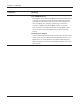
Chapter 4 Configuration IP Filter (Router Mode only) The screen to edit IP filters which relates to the packets passing through the LAN side and the Internet side. Parameter Meaning Log Output If enabled, IP filter activity is saved to a log. Operation Specify how to process target packets. Direction Specify the transmission direction of target packets. IP Address Specify the sender's IP address and receiver's IP address of the target packets.
Chapter 4 Configuration VPN Pass Through (Router Mode only) The screen to configure IPv6 pass through, PPPoE pass through, and PPTP pass through. Parameter Meaning IPv6 Pass Through Enable to use IPv6 Pass Through for address translation. PPPoE Pass Through Enable to use PPPoE bridge.
Chapter 4 Configuration LAN Config (Router Mode only) Port Forwarding (Router Mode only) The screen to configure the port translation. Parameter Meaning Group Specify a group name for a new rule to belong to. Select "New Group" and enter the new group name in the Group Name field to create a new group. A group name can include up to 16 alphanumeric letters. Internet Side IP Address Enter the Internet side IP address (before translation) for the port translation table entry.
Chapter 4 Configuration Parameter Meaning LAN Side IP Address Enter the LAN side IP address (after translation) for the port translation table entry. LAN Side Port Select the LAN side (after translation) port number (1 - 65535) for the port translation table entry. Port Forwarding Registration Information Shows current entries in the port translation table. DMZ (Router Mode only) The screen to configure a destination to transfer communication packets without a LAN side destination.
Chapter 4 Configuration UPnP (Router Mode only) The screen to configure UPnP (Universal Plug and Play). Parameter Meaning UPnP Enable or disable Universal Plug and Play (UPnP) functionality.
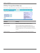
Chapter 4 Configuration QoS (Router Mode only) The screen to configure the priority control of packets sent to the Internet. Parameter Meaning QoS for transmission to the Internet Determine whether or not control the priority of packets to send to the Internet. Check this box to enable QoS. Upload bandwidth Specify the upstream bandwidth in kbps from the AirStation to the internet side. * Set the actual value for the upstream bandwidth. Enable Enable or disable this entry.
Chapter 4 Configuration Parameter Meaning destination port Specify a destination port with the value of 1 - 65535. If this field is empty, a random port is selected. priority Select high, medium or low. * If packets do not qualify for classification as a type on the list, then their priority is treated as a level between medium and low. Admin Config Name The screen to configure the AirStation’s name. Parameter Meaning AirStation Name Enter a name for the AirStation.
Chapter 4 Configuration Password The screen to configure the password to login to the configuration screen of the AirStation. Parameter Meaning Administrator Name The user name to log in to the configuration screen of the AirStation. This name is fixed as “root”. Administrator Password The password to log in to the configuration screen of the AirStation. The password may contain up to 8 alphanumeric characters and underscores (_).
Chapter 4 Configuration Time/Date The screen to configure the internal clock in the AirStation. Parameter Meaning Local Date You may manually set the date of the AirStation’s internal clock. Local Time You may manually set the time of the AirStation’s internal clock. Time Zone Specify the time zone (offset of Greenwich Mean Time) of the AirStation's internal clock.
Chapter 4 Configuration NTP The screen to configure an NTP server to automatically synchronise the AirStation’s internal clock. Parameter Meaning NTP Functionality Enable to use an NTP server to automatically set the AirStation's internal clock. NTP Server Enter the name of the NTP server as a host name, host name with domain name, or IP address. Up to 255 alphanumeric characters, hyphens (-), and underscores (_) may be used.
Chapter 4 Configuration Access The screen to restrict access to the AirStation’s settings screens. Parameter Meaning Log Output Enabling outputs a log of changes to access settings. Prohibit configuration from wireless LAN If enabled, prevents access to settings screens from wirelessly connected devices (only wired devices may configure). Prohibit configuration from wired LAN If enabled, prevents access to settings screens from wired devices (only wirelessly connected devices may configure).
Chapter 4 Configuration Log The screen to transfer the log information of the AirStation by the syslog. Parameter Meaning Log Transfer Enable to send logs to a syslog server. Syslog Server Indentify the syslog server by host name, host name with domain name, or IP address. You may enter up to 255 alphanumeric characters, hyphens (-), and underscores (_). Transfer Logs Choose which logs will be transferred to the syslog server.
Chapter 4 Configuration Save/Restore The screen to save to or restore from an AirStation configuration file. Parameter Meaning Save current settings Clicking "Save" will save the current configuration of the AirStation to a file. If the “Encrypt the configuration file with a password” option is checked, then the configuration file will be password protected with the current Administrator Password (page 57).
Chapter 4 Configuration Initialize/Restart The screen to initialize and restore the AirStation. Parameter Meaning Restart Click "Restart Now" to restart the AirStation. Initialize Click "Initialize Now" to initialize and restart the AirStation.
Chapter 4 Configuration Update The screen to update the AirStation’s firmware. Parameter Meaning Firmware Version Displays the current firmware version of the AirStation. Firmware File Name Click "Browse" to specify a firmware file and click "Update Firmware." This will update the firmware.
Chapter 4 Configuration Diagnostic System Info The screen to verify the system information of the AirStation.
Chapter 4 Configuration Parameter Meaning Model Displays the product name of the AirStation and the firmware version. AirStation Name Displays AirStation Name (refer to page 55). Hardware Mode Switch Status Displays the status of the mode switch on the back of the AirStation. Operational Mode Displays the current operational mode of the AirStation. Internet Displays the information about the Internet port. LAN Displays the information about the LAN port.
Chapter 4 Configuration Log The screen to check log information recorded by the AirStation. Parameter Meaning Display log info Choose the types of log information to display. Logs Displays the log information recorded in the AirStation.
Chapter 4 Configuration Packet Info The screen to verify the total amount of packets the AirStation transfers. Parameter Meaning Sent Displays the number of packets sent to the Internet side of Ethernet, the LAN side of the Ethernet, and the LAN side of the wireless connection. Received Displays the number of packet received from the Internet side of Ethernet, the LAN side of the Ethernet, and the LAN side of the wireless connection.
Chapter 4 Configuration Client Monitor This screen shows devices that are connected to the AirStation. Parameter Meaning Client Monitor Displays information ( MAC address, lease IP address, host name, communication method, wireless authentication and 802.11n) for devices that are connected to the AirStation.
Chapter 4 Configuration Ping A Ping test checks whether the AirStation can communicate with a specific network device. Parameter Meaning Destination Address Enter an IP address or a host name of the device for which you try to verify the connection, and click "Execute". The result will be displayed in the “Result” field.
Chapter 5 Connect to a Wireless Network Automatic Secure Setup (AOSS/WPS) AOSS and WPS are systems which enables you to automatically configure wireless LAN settings. Just pressing the buttons will connect wireless devices and complete security settings. Utilize this system to connect to wireless devices, computers, or game machines which support AOSS or WPS. AOSS (AirStation One-Touch Secure System) is technology developed by BUFFALO. WPS was created by the Wi-Fi Alliance.
Chapter 5 Connect to a Wireless Network Windows Vista (Client Manager V) If you are using Windows Vista, use the included Client Manager V software to connect wirelessly with AOSS/WPS. 1 Click the icon 2 3 in the system tray. When the screen at left is displayed, click “Create Profile”. When the message "A Program needs your permission to continue" appears, click “Continue”. 4 When the screen shown at left is displayed, click the “WPS AOSS “ button. Follow the instructions displayed on the screen.
Chapter 5 Connect to a Wireless Network Windows XP (Client Manager 3) If you are using Windows XP, use the included Client Manager 3 software to connect wirelessly with AOSS/WPS. 1 Right click on the icon displayed in the system tray, and select “Profile”. 2 When the screen shown at left is displayed, click “WPS AOSS” button. Follow the instructions displayed on the screen.
Chapter 5 Connect to a Wireless Network Other Devices (e.g. Game Console) If you are using a game machine which supports AOSS or WPS, refer to that device’s manual to initiate AOSS/WPS. When instructed, hold down the AOSS button (page 11) on the AirStation for 1 second. After you configure the settings and the SECURITY LED (on page 8) stops blinking and is lit, the AOSS/WPS connection is completed.
Chapter 5 Connect to a Wireless Network If the screen below is displayed, click “I want to enter the network key or passphrase instead”.
Chapter 5 Connect to a Wireless Network 4 When the screen at left is displayed, enter an encryption key (such as WEP key or pre-shared key) and click “Connect”. Follow the instructions displayed on the screen to finish configuration. (If the Set Network Location screen is displayed, select “Home”, “Work”, or “Public location“ depending where you’re using the AirStation.
Chapter 5 Connect to a Wireless Network Windows XP (Wireless Zero Configuration) Windows XP includes a built-in utility to connect to your AirStation. Note: If Client Manager 3 is installed on your computer, Windows Zero Config is disabled. Uninstall Client Manager 3 to use Windows Zero Config, or just use Client Manager 3 to connect to the AirStation. 1 Right click on the wireless network icon displayed in the system tray. 2 Click “View Available Wireless Networks”.
Chapter 6 Trouble Shooting Cannot connect to the Internet over wired connection.
Chapter 6 Trouble Shooting Cannot connect to the network wirelessly. • Configure your wireless device with the same SSID, encryption type, and encryption key as used by your AirStation. The following are the factory default settings of the AirStation: SSID - Encryption Method Encryption Key - Printed on the label of the AirStation WPA-PSK (AES) Printed on the label of the AirStation • Place your AirStation and wireless devices 2 - 10 feet apart. • Restart your AirStation.
Chapter 6 Trouble Shooting Other Tips Issue: I reset my wireless router to factory settings and forgot how to log in. Answer: Open your browser and enter 192.168.11.1 as the browser address and hit Enter. You will be prompted to log in. Enter the user name as root and the password box is left empty (no password). Click "OK" to complete the login and the option to reset your password will be available on the first page.
Chapter 6 Trouble Shooting Issue: What can I do if my wireless connection drops randomly or seems slow? Answer: There are many environmental factors that may affect this behavior. First, ensure the issue is not range related by locating the wireless router and the device dropping connection in closer proximity and check whether the connection drops continue. In some cases, interference from other wireless networks or sources such as 2.4 GHz wireless phones may impact performance.
Chapter 6 Trouble Shooting Issue: Where can I download the latest drivers, firmware and instructions for my Buffalo wireless products? Answer: The latest drivers and firmware are available online at www.buffalotech.
Appendix A Specifications Wireless LAN Interface Standard Compliance IEEE802.11b / IEEE802.11g / IEEE802.11n (Draft 2.0) Transmission Method Direct Sequence Spread Spectrum (DSSS), OFDM, MIMO Frequency Range 2,412 - 2,462MHz (Channels 1 - 11) Transmission Rate 802.11b/g: 54, 48, 36, 24, 18, 12, 9, 6, 11, 5.5, 2, 1Mbps 802.11n (Draft 2.0) 20MHz BW (ShortGI) 65, 72.2, 57.8, 43.3, 28.9, 21.7, 14.4, 6.5Mbps (1stream) 40MHz BW (LongGI) 135, 121.5, 108, 61, 54, 40.5, 27, 13.
Appendix B Default Configuration Settings Feature Parameter Default Setting Internet Method of Acquiring IP Address Perform Easy Setup (Internet Connection Wizard) Default Gateway none Address of DNS Name Server none Internet MAC Address Use Default MAC Address Internet Communication Format SPEED: Auto MTU Size of Internet Port 1500 Bytes Default PPPoE Connection No Active Session IP Unnumbered PPPoE Connection No Active Session PPPoE Connection List none Preferred Connections none D
Appendix B Default Configuration Settings Feature Parameter Default Setting DHCP IP Address Pool 192.168.11.
Appendix B Default Configuration Settings Feature Advanced WMM Parameter Default Setting 300Mbps Mode Band Width: 20MHz Extension Channel: - Broadcast SSID Allow Separate feature not used SSID Configure AirStation's MAC address Wireless authentication WPA-PSK Wireless encryption AES WPA-PSK (Pre-Shared Key) A 13-digit random value (Printed on the label of the AirStation) Rekey interval 60 minutes BSS Basic Rate Set 1,2,5.
Appendix B Default Configuration Settings Feature Parameter WMM-EDCA Parameters (Priority AC_VI (High) ) WMM-EDCA Parameters (Priority AC_VO (Highest) ) MAC Filter Default Setting For AP For STA CWmin 7 7 CWmax 15 15 AIFSN 1 2 TXOP Limit 94 94 Admission Control ----- Disable For AP For STA CWmin 3 3 CWmax 7 7 AIFSN 1 2 TXOP Limit 47 47 Admission Control ----- Disable Enforce MAC Filter Disable Registration List none Multicast Control Snooping Enable Multicast Ag
Appendix B Default Configuration Settings Feature Parameter Default Setting Name AirStation Name AP + AirStation's MAC Address Password Administrator Name root (fixed) Administrator Password none Local Date 2008 Year 1 Month 1 Day Local Time 0 Hour 0 Minute 0 Seconds Time Zone (GMT+00:00) Greenwich Mean Time, London NTP Functionality Disable NTP Server none Update Interval 24 hours Log Output Disable Limitation Item Prohibit configuration from wireless LAN Prohibit configuration f
Appendix C TCP/IP Settings in Windows Windows Vista To perform the settings for Windows Vista, follow the procedure below. 1 Click Start > Settings > Control Panel. 2 Double click “Network and Sharing Center”. 3 Click “Manage network connections” on the left side menu. 4 Right click on “Local Area Connection”, then click “Properties”. 5 When the message “Windows needs your permission to continue”, click “Continue”. 6 Select “Internet Protocol Version 4 (TCP/IPv4)” then click “Properties”.
Appendix C TCP/IP Settings in Windows Windows XP To perform the settings for Windows XP, follow the procedure below. 1 Click Start > Settings > Control Panel. 2 Double click “Network”. 3 Right click on “Local Area Connection”, then click “Properties”. 4 Select “Internet Protocol (TCP/IP)”, then click “Properties”. 5 Select “Obtain an IP address automatically” and “Obtain DNS server address automatically”, and then click “OK”. 6 Click “Close”.
Appendix D Restoring the Default Configuration ᵏᵂᵐᵂᵑ Hold down this button for 5 seconds. The AirStation will be initialized.
Appendix E Regulatory Compliance Information Federal Communication Commission Interference Statement This equipment has been tested and found to comply with the limits for a Class B digital device, pursuant to Part 15 of the FCC Rules. These limits are designed to provide reasonable protection against harmful interference in a residential installation.
Appendix E Regulatory Compliance Information European Union Notice: This device complies with the essential requirements of the R&TTE Directive 1999/5/EC.
Appendix E Regulatory Compliance Information Česky[Czech] Buffalo Technology Inc. tímto prohlašuje, že tento AirStation WHR-HP-GN je ve shodě se základními požadavky a dalšími příslušnými ustanoveními směrnice 1999/5/ES. Dansk[Danish] Undertegnede Buffalo Technology Inc. erklærer herved, at følgende udstyr AirStation WHR-HP-GN overholder de væsentlige krav og øvrige relevante krav i direktiv 1999/5/EF. Deutsch[German] Hiermit erklärt Buffalo Technology Inc.
Appendix E Regulatory Compliance Information Lietuvių[Lithuanian] Šiuo Buffalo Technology Inc. deklaruoja, kad šis AirStation WHR-HP-GN atitinka esminius reikalavimus ir kitas 1999/5/EB Direktyvos nuostatas. Nederlands[Dutch] Hierbij verklaart Buffalo Technology Inc. dat het toestel AirStation WHR-HP-GN in overeenstemming is met de essentiële eisen en de andere relevante bepalingen van richtlijn 1999/5/EG. Malti[Maltese] Hawnhekk, Buffalo Technology Inc.
Appendix E Regulatory Compliance Information Industry Canada statement This device complies with RSS-210 of the Industry Canada Rules. Operation is subject to the following two conditions: (1) This device may not cause harmful interference, and (2) this device must accept any interference received, including interference that may cause undesired operation. IMPORTANT NOTE: Radiation Exposure Statement: This equipment complies with IC radiation exposure limits set forth for an uncontrolled environment.
Appendix E Regulatory Compliance Information TERCERA -Los equipos amparados por este Certificado de Homologación deberán tener indicado en alguna parte visible, firmemente adherido, el númerode Certificado de Homologación correspondiente, así como la marca y modelo con la que se expide este Certificado.
Appendix F Environmental Information • The equipment that you have purchased has required the extraction and use of natural resources for its production. • The equipment may contain hazardous substances that could impact health and the environment. • In order to avoid the dissemination of those substances in our environment and to diminish the pressure on the natural resources, we encourage you to use the appropriate take-back systems.
Appendix G GPL Information The source code for Buffalo products that use GPL code is available at http://opensource.buffalo.jp/ .
Appendix H Warranty Information Buffalo Technology (Buffalo Inc.) products come with a two-year limited warranty from the date of purchase. Buffalo Technology (Buffalo Inc.) warrants to the original purchaser the product; good operating condition for the warranty period. This warranty does not include non-Buffalo Technology (Buffalo Inc.) installed components. If the Buffalo product malfunctions during the warranty period, Buffalo Technology/(Buffalo Inc.
Appendix I Contact Information North America Buffalo Technology USA Inc. 11100 Metric Blvd, Suite 750 Austin, TX 78758 GENERAL INQUIRIES Monday through Friday 8:30am-5:30pm CST Direct: 512-794-8533 | Toll-free: 800-456-9799 | Fax: 512-794-8520 | Email: sales@buffalotech.com TECHNICAL SUPPORT North American Technical Support by phone is available 24 hours a day, 7 days a week. (USA and Canada). Toll-free: (866) 752-6210 | Email: info@buffalotech.
Appendix H Contact Information Europe Buffalo Technology UK Ltd. 2 Bracknell Beeches, Old Bracknell Lane Bracknell, Berkshire, RG12 7BW United Kingdom GENERAL INQUIRIES Email: sales@buffalo-technology.com TECHNICAL SUPPORT Buffalo Technology provides technical support in English, German, French, Italian, and Spanish. For opening hours and relevant telephone numbers, please go to www.buffalo-technology.