
Manual


SECTION 2 - OPERATION
2-35
Ground Speed Calibration (Non-Radar Tractors
Only)
The ground speed in the display is calibrated in the
factory to suit the static radius of the rear tires.
However, should tires of a different size be installed,
weights or equipment permanently installed on the
tractor that would alter the static r adius of the tires by
more than 6 mm (0.25″), the EIC should be
recalibrated to display a more accurate ground
speed using the following method:
Ensure that the tire pressures are correct for the load
being carried. See “Tire Load/Inflation Tables” in
Section 5.
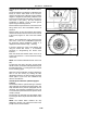
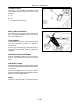
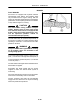
Park the tractor on a firm level surface and carefully
measure the distance from the center of the rear hub
to the ground, Figure 54. This is the static loaded
radius.
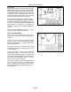
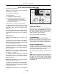
While in the programming mode, ensure that the
word “CAL,” 4, the “FT, 3, or METERS” legend and
the previously entered calibration number, 2, is
displayed with the left-hand digit, 1, flashing.
If required, change the value of the flashing digit
using the DIGIT SET switch, 7, as described
previously in “Programming the Service Alert
Indicator.”
Enter the actual static loaded radius of the tire in
inches to the closest 0.1″ or to the closest mm if using
metric units.
NOTE: The minimum allowable number is 641 mm
(26
″
).
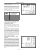
To select the next digit to the right, use the DIGIT
SELECT switch, 6, and when that digit is flashing use
the DIGIT SET switch, 7, to change the value. Repeat
for the remaining digits.
When the required calibration number is displayed,
enter it into the memory by holding the SET
UP/SELECT switch, 5, for three seconds. Touch the
switch again to cycle to the next calibration step
which is “Area Preset.”
Ground Speed Calibration (Radar-Equipped
Tractors)
Tractors fitted with the optional radar gun automati-
cally recalculate and change the loaded radius. The
steps described in the previous paragraphs are not
necessary. This automatic recalculation occurs over
a 15-minute time period when tractor speed is above
16 Kph (10 mph).
The operator can manually reset the loaded radius
by zeroing the wheel slip as described earlier in this
section.
NOTE: The loaded radius numbers are only
displayed in the EIC. The values are stored in the
(CCM) Chassis Control Module.
53
54