WARRANTY REGISTRATION AND POLICY Buhler Manufacturing products are warranted for a period of twelve (12) months from original date of purchase, by original purchaser, to be free from defects in material and workmanship under correct, normal agricultural use and proper applications. Buhler Manufacturing’s obligations under this warranty shall be limited to the repair or exchange, at Buhler Manufacturing’s option, of any Buhler Manufacturing product or part which proves to be defective as provided.
bühler Allied Front-End Loader 2895E OPERATOR’S AND PARTS MANUAL Table of Contents Description Page Registration and Policy Loader Specifications .......................................................................................... 2 Introduction Terminology .............................................................................................. Serial Decal Location ................................................................................ 4 5 Safety General Safety Notes ............
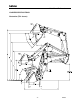
bühler Allied Front-End Loader LOADER SPECIFICATIONS Illustration (TSL shown) -2- P4493
bühler Allied Front-End Loader Specification Chart A Maximum lift height to pivot pin [in/cm] 2895E REG 181/460 B Maximum lift height under level bucket [in/cm] 172/437 172/437 160/406 160/406 C Clearance with bucket dumped [in/cm] 146/370 146/370 134/340 134/340 20/51 Item Description 2895E TSL 181/460 2895E S REG 169/429 2895E S TSL 169/429 D Reach at maximum lift height [in/cm] 29/74 29/74 20/51 E Maximum dump angle [deg] 62 61 62 61 G Maximum rollback angle [deg] 37 37
bühler Allied Front-End Loader INTRODUCTION This manual has been provided as information regarding the specifications, safe operation and maintenance of your agricultural front-end loader. Read and understand this manual and the tractor manual prior to operating to obtain the best use of operating your loader. Keep this manual for reference and to forward to new operators and owners. Contact your local Buhler - Allied dealer if you require any assistance, information or additional manuals.
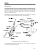
bühler Allied Front-End Loader Serial Decal Location: The serial decal is located on the inside left arm of the loader joint plate. Please record the serial number in the space provided for future reference. The serial decal will provide the model and date of manufacture of the loader and will be required to obtain correct replacement parts and complete warranty claims.
bühler Allied Front-End Loader SAFETY Read and understand all the safety messages listed in this manual. For your safety and the safety of others near the machine, learn how to control and operate the loader properly. It is your responsibility to inform subsequent operators and owners of these precautions. General Safety Notes: 9 Improper use of the loader and tractor can cause serious injury or death. 9 Operate the loader while seated in the tractor seat only. 9 Keep the work area clear of other persons.
bühler Allied Front-End Loader Safety Decals: Safety Decal Location illustrates the approximate location and detail of safety decals. To install safety decals ensure the installation area is clean and dry. Decide on the exact position before you remove the backing paper. Remove the smallest portion of the split backing paper and align over the specified area. Carefully press in place. Slowly peel back the remaining paper and smooth the remaining portion in place.
bühler Allied Front-End Loader Safety Decal Location -8- P4493
bühler Allied Front-End Loader The following pictorials indicate important precautions to be used during the operation of the loader. WARNING DANGER FALLING HAZARD ELECTROCUTION HAZARD To prevent serious injury or death: To prevent serious injury or death: Stay away from power lines and cables. Electrocution can occur with or without direct contact. Do not lift, carry or allow anyone to ride on or work from any portion of loader.
bühler Allied Front-End Loader PRE – OPERATION WARNING The tractor must be equipped with an approved Roll over Protection Structure (ROPS) and safety belts to help prevent personal injury or death caused by tractor roll over. CAUTION Maximum rated loader capacity may exceed tractor rating. Load restrictions or reduction in hydraulic operating pressure may be required for safe operation. Rops: Do not exceed the manufacturer’s rating for maximum gross vehicle weight.
bühler Allied Front-End Loader OPERATION General Operating Notes: The following section provides general information that can be applied towards your specific application. Ensure that you’ve read and understood this manual and your Tractor Manual. Observe all safety precautions and follow local laws pertaining to the use of your loader and tractor. Hydraulics: Under normal conditions, operate the tractor’s engine at ½ throttle.
bühler Allied Front-End Loader All Buhler-Allied hydraulic valves are self-centering and return to neutral from all positions except float. The float or detent spool is only to be used on the boom circuit. This position allows the oil to freely flow through the valve so the lift cylinders can extend or retract. It can be engaged by slightly pushing control beyond full lower. Float will allow for the loader to lower and rise as the attachment follows the ground contours.
bühler Allied Front-End Loader Minimize turning angle and length of run between pile and trailer to increase loading efficiency. Also, place load evenly or centered in the attachment. WARNING Carry the load no higher than necessary to clear the terrain. Turn and brake slowly. Always be sure that loading area is level and on solid ground. Do not raise loader higher then required while dumping. Immediately lower the loader to ground if the tractor becomes unstable.
bühler Allied Front-End Loader For back grading, either load the bucket and position the heel on the ground or position the bucket at 40q or less below level as shown. Place the valve in the float position and back up slowly. IMPORTANT: Float position must be used to reduce down pressure, otherwise cylinder rod(s) and/or bucket damage could occur. A – Frame: Standard and Heavy Duty A – Frames can be fitted with either spears or pallet forks.
bühler Allied Front-End Loader Handling bales and pallets: For safe handling of bales and pallets please follow procedures below: WARNING Do not operate A – Frame for bales without the stabilizers. With a single spear, enter one of the ends of the bale and drive the spear horizontally into the center or slightly above center of the bale and fully penetrate the bale. Then rollback the bucket cylinders approximately three quarters of the cylinder stroke and lift bale approximately a foot off the ground.
bühler Allied Front-End Loader When loading bales onto a trailer, park trailer in close proximity to minimize turning angle and length of travel to increase loading efficiency. As you lift the bale using the regular loader, it is recommended to feather the valve to allow bucket cylinders to extend to keep bale at about a 20q angle. (On TSL loaders this is not necessary) Lift the bale only enough to clear the area that the bale will be placed on. Always approach the trailer square to the tractor as shown.
bühler Allied Front-End Loader Grapple: The grapple is designed to safely prevent loads (bales, silage) from falling out of the bucket. (Refer to pictorial below for options listed) WARNING Travel at low speeds. Carry loads as low as possible. Avoid sharp turns and uneven terrain. Grapple for Hay or Silage Standard Euro Quick attach brackets (2495E-2895E) Standard 495-995 Quick attach Optional 95-395 Quick attach Optional factory pre punched grapple buckets.
bühler Allied Front-End Loader INSTALLING / REMOVING LOADER Installing: CAUTION Prior to initial mounting, cycle loader cylinders to displace air. This ensures the loader will remain in the storage position and operate consistently. 1. Position the tractor centrally and parallel to the loader uprights. Drive forward slowly until the loader hydraulic hoses can be coupled. Shut tractor off and set park brake.
bühler Allied Front-End Loader 5. With the tractor in neutral, continue to retract the lift cylinders and extend the bucket cylinders to rotate the upright back against the lock pin stops. Shut the tractor off and set park brake. 6. Install both upright attachment pins and secure with hairpin clip. Start the tractor and slowly raise loader until the parking stands are off the ground.
bühler Allied Front-End Loader 2. Lower attachment level to the ground while engaging float position. Ensure attachment rests firmly on ground with minimal downward pressure. If required extend bucket cylinders to rotate upright rearward. At this stage the pin should have no pressure. Set tractor park brake and remove loader lock pins. Check hydraulic hoses such that they will not get pinched or stretched during removal. WARNING Operate hydraulic controls slowly.
bühler Allied Front-End Loader INSTALLING / REMOVING LOADER ATTACHMENTS Installing: 1. Position tractor centrally within the bucket hooks. Dump Quick-tach slightly from vertical position. Slowly drive the tractor forward until the Quick-tach contacts the bucket. 2. Slowly raise the loader to engage the Quick-tach within both bucket hooks. When both hooks are resting on the Quick-tach rollback the bucket. Shut tractor off. Lock using both Quick-tach pins and secure with hairpin clips.
bühler Allied Front-End Loader LUBRICATION Lubricate loader bushings and pivots every eight hours of average operation with high-grade grease. For grease fitting locations see illustration below. Select grease based on the expected outside temperature range. Lithium, Molybdenum and synthetic greases are preferred. Use the tractor hour meter as a guide. Increase lubrication intervals for extreme use or adverse conditions. Each pivot should be lubricated until grease is visible at pin.
bühler Allied Front-End Loader MAINTENANCE General Inspection: CAUTION Lower attachment and loader to ground, place all controls in neutral, stop engine, set parking brake and remove ignition key before inspecting, servicing, adjusting or repairing loader. WARNING Relieve hydraulic pressure before repairing, adjusting or disconnecting hydraulics components. Escaping hydraulic oil can penetrate skin causing serious personal injury. If injured consult a physician immediately.
bühler Allied Front-End Loader Mounting Kit: After the initial 2 weeks or 40 hours of loader operation, and 6-month intervals thereafter re-torque all mounting kit bolts. (See below for proper bolt torques) Bolt Torque Chart: Standard Grade 2 Bolts Bolt Size Torque (in.) ft-lbs NM 6 7 0.25 11 15 0.313 20 27 0.375 32 43 0.438 49 66 0.5 70 95 0.563 97 131 0.625 144 195 0.75 166 225 0.875 250 339 1 354 480 1.125 500 678 1.25 655 887 1.375 870 1179 1.
bühler Allied Front-End Loader Hydraulics: WARNING Escaping fluid under pressure can have sufficient force to penetrate the skin, causing serious personal injury. Before repairing, adjusting, or disconnecting lines, be sure to relieve all pressure. Before applying pressure to the system, be sure all connections are tight and the lines, pipes, and hoses are not damaged. Wear proper hand and eye protection when searching for leaks. Use a piece of wood or cardboard instead of hand to check for leaks.
bühler Allied Front-End Loader A yearly inspection of the valve is recommended. However the maintenance intervals on the valve depends on the surrounding environment or if valve spools become stiff. Where temperatures fluctuate from one extreme to another or exposed to high salt the intervals for maintenance should be increased to protect from corrosion. On non-cab tractors mounted with the joystick valve, slip back the boot and clean away any debris.
bühler Allied Front-End Loader On valves fitted with joystick cables loosen off jam nut and cable sleeves to gain access to the valve spool. Clean all debris and any existing corrosion. Spray areas with a light corrosion resistant lubricant. Re-mount cables sleeves and adjust so that joystick is centered in both axis to the base. Lock cable sleeve by using the jam nut. Note: In severe cold weather climates, inspect and maintain the valve and joystick cables before cold weather.
bühler Allied Front-End Loader TSL GENERAL NOTE AND INSTRUCTIONS 1. The true self leveling system (TSL) utilizes mechanical linkages to maintain bucket level while raising and lowering. The pivot plate weldment, leveling tubes and linkages have been developed to ensure that the bucket remains at the same position throughout its range of motion. This feature is standard with 2.50” and 3.00” diameter bucket cylinders. 2.
bühler Allied Front-End Loader TROUBLE SHOOTING Problem Loader slow and/or will not dump. Possible Cause Quick couplers leaking Hydraulic oil too heavy. Oil filter plugged. Hydraulic pump worn. Oil line restricted or leaking. Control valve does not shift properly. Air in hydraulic system. Cylinder leaks internally. Faulty valve. Remedy Check connections and compatibility or replace. Change or replace filter. Clean or replace filter. Repair or replace pump.
bühler Allied Front-End Loader Trouble Shooting Continued Problem Insufficient lift capacity. Possible Cause Remedy Improper hydraulic pump operation. Load is greater than boom lift capacity. Internal boom cylinder leakage. Improper hydraulic valve operation. Repair or replace pump. Slow leak down. Worn control valve. Worn cylinder piston seals. Have authorized dealer replace seals. Excessive wear on bottom of bucket and wear pads. Float position not used while operating loader.
bühler Allied Front-End Loader 2895E & 2895E S PARTS APPENDIX Description Page 2895E & 2895E S Main Frame Assembly .............................................................................. 32 Hydraulic Plumbing ................................................................................... 34 2895E TSL & 2895E S TSL Main Frame Assembly .............................................................................. 36 Hydraulic Plumbing .............................................................
bühler Allied Front-End Loader 2895E & 2895E S Main Frame Assembly 5 - 32 - P4493
bühler Allied Front-End Loader 2895E & 2895E S Main Frame Assembly Item Part No. 1 1 2 3 4 5 6 7 8 9 10 11 12 13 14 15 16 17 18 19 20 21 22 23 24 25 26 27 28 29 30 31 32 33 34 35 36 37 38 39 40 41 42 24966 24944 25388 Ref. Ref.
bühler Allied Front-End Loader 2895E & 2895E S Hydraulic Plumbing Assembly - 34 - P4493
bühler Allied Front-End Loader 2895E & 2895E S Hydraulic Plumbing Assembly Item Part No. 1 2 3 4 4 5 5 6 7 7 8 8 9 9 10 11 12 13 14 15 16 17 Ref. Ref.
bühler Allied Front-End Loader 2895E TSL & 2895E S TSL Main Frame Assembly 45 45 - 36 - P4493
bühler Allied Front-End Loader 895E TSL & 2895E S TSL Main Frame Assembly Item Part No. 1 1 2 3 4 5 6 7 8 9 10 10 11 12 13 14 15 16 17 18 19 20 21 22 23 24 25 26 27 28 29 30 31 32 33 34 35 36 37 38 39 40 41 42 43 44 45 46 24967 24945 25388 Ref. Ref.
bühler Allied Front-End Loader 2895E TSL & 2895E S TSL Hydraulic Plumbing Assembly A 7 B 13 16 17 B 15 13 10 4 9 4 3 3 14 6 5 2 11 12 VIEW A-A - 38 - P4493
bühler Allied Front-End Loader 2895E TSL & 2895E S TSL Hydraulic Plumbing Assembly Item Part No. 1 2 3 4 5 5 6 6 7 8 8 9 9 10 10 11 12 13 14 15 16 17 18 19 20 21 22 23 24 25 26 27 Ref. Ref.
bühler Allied Front-End Loader Possible Attachment Interference (2895E TSL & 2895E S TSL) Regular loader linkage setup allows for maximum rollback. TSL loader linkage setup provides reduced rollback. When fully rolled back, large attachments (such as the C2000 Grapple) may contact the 2895E TSL or the 2895E S TSL pivot plate. This interference is avoided in factory assembly by installing the linkages (item 12) in the limited rollback position.
bühler Allied Front-End Loader 2895E Cylinder Assembly Bucket Cylinders Regular 3.00" 27.50" 38.75" 66.25” 25166 X1424 1.75" TSL 3.00” 24.50" 52.25" 76.75" 25186 X1424 1.
bühler Allied Front-End Loader Hydraulic Fitting Torques: Dash Size Thread Size -04 -05 -06 -08 -10 -12 -14 -16 -20 -24 7/16-20 1/2-20 9/16-18 3/4-16 7/8-14 1-1/16-12 1-3/16-12 1-5/16-12 1-5/8-12 1-7/8-12 Jam Nut or Straight ORB Fitting Torque (ft-lbs) (NM) 14-16 20-22 18-20 24-27 24-26 33-35 50-60 68-78 72-80 98-110 125-135 170-183 160-180 215-245 200-220 270-300 210-280 285-380 270-360 370-490 SAE 37° (JIC) Swivel Nut Torque (ft-lbs) (NM) 10-11 13-15 13-15 18-20 17-19 23-26 34-38 47-52 50-56 69-76 7
DIVISION LOCATIONS U.S. WAREHOUSES Allied Division 1201 Regent Ave. W. Box 1003 Winnipeg, MB R2C 3B2 Ph.: (204) 661-8712 Fax: (204) 654-4331 AR, West Memphis (870) 732-3132 NC, Dunn (910) 892-8500 GA, Stone Mountain (770) 908-9439 NC, Statesville (704) 873-0531 IA, Atlantic (712) 243-5520 ND, Bismarck (701) 223-1886 Farm King Division 301 Mountain Street S. Morden, MB R6M 1X7 Ph.