85” Snowblower TABLE OF CONTENTS DESCRIPTION PAGE Warranty ......................................................................1 Safety Instructions .......................................................2 Safety Sign Locations ..................................................3 Assembly Instructions ..................................................4 Operating Instructions ..................................................5 85” Allied Snowblower Drawings..................................
85” Snowblower WARRANTY POLICY Buhler Manufacturing products are warranted for a period of twelve (12) months (90 days for commercial application) from original date of purchase, by original purchaser, to be free from defects in material and workmanship under correct, normal agricultural use and proper applications.
85” Snowblower CAUTION 1. Always review operator’s manual before starting new machine. 2. Do not let inexperienced operators or children run this equipment. 3. Never service or clean unit while it is running. 4. Do not remove shields. 5. Stay clear of augers. 6. Stay clear of discharge chute. Rocks can be picked up and thrown. 7. Poor judgment results in accidents. Always be careful. 8. Remember a careful operator is the best insurance.
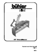
85” Snowblower SNOWBLOWER This manual covers the 85” model snowblower. When ordering parts, be sure to list the serial number of your unit and blower width. The snowblower is the push type and will mount to a tractor with a category 1 or 2 three point hitch and 540 rpm PTO. The 85" model has a single auger and comes with a hydraulic control for the chute with a manual control available as an option.
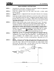
85” Snowblower BASIC ASSEMBLY INSTRUCTIONS STEP 1. STEP 2. STEP 3. STEP 4. STEP 5. STEP 6. STEP 7. Assemble the snow chute, referring to instructions under the appropriate heading for “manual chute” or “hydraulic chute”. Check the gearbox and fill to the lower level with a winter grade transmission oil. The snowblower is shipped with lower three point hitch pins for a category 2 hitch.
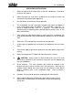
85” Snowblower OPERATING INSTRUCTIONS 1. Adjust the top link of the tractor hitch so that the snowblower is level when resting on the ground. 2. Adjust the lower link sway chains or blocks on the tractor to restrict side movement of the blower when operating. 3. Run the blower at low RPM to check operation. 4. The snowblower has two shear bolts to protect the tractor and blower in case a large object enters the blower.
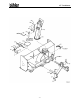
5” Snowblower 85" ALLIED SNOWBLOWER -6-
85” Snowblower -7-
85” Snowblower WHEN ORDERING PARTS Always give your dealer the Model, Color and Serial Number of your machine to assist him in ordering and obtaining the correct parts. Use the exploded view and tabular listing of the area of interest to exactly identify the required part.
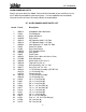
85” Snowblower 33 34 35 36 37 38 39 40 41 42 43 44 45 46 47 48 49 50 51 52 53 54 55 56 57 58 59 60 61 62 63 64 65 66 67 81636 812364 81592 84217 812362 81701 81678 81637 81593 936402 965911 988999 BU50505 81677 F842 965648 965970A 961658 965646 961876 903523 961012 81569 81568 24930 115370 902407 900712 967164 108979 107780 967140 81210 86171 812026 1/2'' Hex Nut (pl) 1/2'' Lock Nut (pl) 3/8'' Hex Nut (pl) 3/8'' Wing Nut (pl) 5/16'' Lock Nut (pl) 3/4'' Lock Washer (pl) 5/8'' B.S.
85” Snowblower MANUAL CHUTE CONTROL 1. 2. 3. 4. 5. 6. 7. 8. Remove spout clamp and install chute. Mount handle brackets to snowblower & hitch. Insert handle extension, placing a 1” flat washer on both sides of the front handle bracket; secure with 3/16 cotter pin. Attach handle to handle extension. Turn chute away from handle. Attach end of cable with cable bolt. Wrap cable clockwise around chute and attach cable to tab on chute with cable clamp. Wrap cable around handle extension 5 complete turns.
85” Snowblower 85'' Manual Chute Control Item # 1 2 3 4 5 6 7 8 9 10 11 12 13 14 15 16 17 18 19 20 21 Part # Description 965648 965970A 102157 108014 108015 108020 108019 108265 81207 811631 961658 812363 81552 81568 81569 84522 84498 965646 961876 961012 903523 Spout Weldment Spout Clamp Crank Handle Handle Extension Handle Bracket Handle Bracket Cable Bolt Chute Cable 3/16'' x 66'' 3/16'' x 2'' Cotter Pin 1/4'' x 1 1/2'' Hex Bolt (pl) 1/4'' Cable Clamp 3/8'' Lock Nut (pl) 5/16'' x 1 1/4'' Hex Bolt (p
85” Snowblower HYDRAULIC SNOW CHUTE NOTE: 1. 2. 3. 4. 5. 6. 7. 8. Before mounting chute, apply a heavy coating of light grease to chute ring. Remove spout clamp and mount chute. Mount pivot arm. NOTE: Flat Washers are supplied for height spacer if required. Connect one end of cable to pivot arm with cable clamp. Wrap cable completely around chute ring. Then return to pivot arm and connect with cable clamp.
85” Snowblower 85'' Hydraulic Chute Control Item # 1 2 3 4 5 6 7 8 9 10 11 12 13 14 Part # Description 965648 965970A 108979 107780 961658 965646 961876 961012 967140 812435 81552 81569 81568 903523 Discharge Chute Spout Clamp Cable Pivot Arm Chute Cable 1/4'' Cable Clamp Spout Adjustment Bar 1/2'' x 1 3/8'' Clevis Pin #16 Hair Pin Clip 1'' Flat Washer 1/4'' x 1 3/4'' Cotter Pin 5/16'' x 1 1/4'' Hex Bolt (pl) 5/16'' Lock Washer (pl) 5/16'' Hex Nut (pl) Adjustment Pin Weldment - 13 -
85” Snowblower 85” ALLIED SNOWBLOWER PTO - 14 -
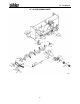
85” Snowblower SNOWBLOWER PTO (STANDARD) Item # Part # 1 2 F842 936263 936264 936277 936199 3 936249 4 5 6 903296 812362 936025 906504 936270 936319 936272 936273 936274 936269 81627 812364 7 8 9 10 11 12 13 14 Description Shaft Complete Tractor Half of PTO (Shear) Implement Half of PTO (Clamp Yoke) Shear Assembly Safety Slide Lock Repair Kit (Collar, Spring, Ret.
85” Snowblower SNOWBLOWER PTO (OPTIONAL LONG) Item # Part # 1 2 F844 936285 936280 936277 936199 3 936249 4 5 6 903296 812362 936025 906504 936281 936319 936282 936283 936284 936269 81627 812364 7 8 9 10 11 12 13 14 Description Shaft Complete Tractor Half of PTO (Shear) Implement Half of PTO (Clamp Yoke) Shear Assembly Safety Slide Lock Repair Kit (Collar, Spring, Ret.
85” Snowblower GEAR BOX ASSEMBLY - 17 -
85” Snowblower GEARBOX ASSEMBLY PARTS LIST - BU50505 Item # 1 2 3 4 5 6 7 8 9 10 11 12 13 14 15 16 17 18 19 20 21 22 23 24 Part # Description BU575901 BU575902 BU50444 BU50417-1 BU50310 BU50502 BU50507 BU50422-1 BU50415 BU50414-1 BU50414-2 BU50414-3 BU50458 BU500397-6 BU50429 BU50329 BU50457 BU500089-3 BU500167-1 BU50428 BU50331 BU575906 BU575907 BU278811 Bearing Cone (13687) Bearing Cup (13620) Staking Lock Nut Key Gear Box Casting Pinion Shaft Cross Shaft Oil Seal Retaining Ring 0.005 Shim 0.
85” Snowblower 1.75 X 5 CYLINDER ASSEMBLY Item # Part # Description 1 2 3 24930 115367 112104 X2669 Cyl Complete Tube Weldt Shaft Weldt 1.0 Dia Seal Kit 3.5 x 8 CYLINDER ASSEMBLY Item # Part # Description 1 2 3 24803 24804 113934 X2098 Cyl Complete Tube Weldt Piston Rod 1.
85” Snowblower 85" ALLIED SNOWBLOWER BUNDLES QUANTITY BUNDLE NO.
DIVISION LOCATIONS Farm King Division 301 Mountain Street S. Morden, MB R6M 1X7 Ph.: (204) 822-4467 Fax: (204) 822-6348 Allied Division 1201 Regent Ave. W. Box 1003 Winnipeg, MB R2C 3B2 Ph.: (204) 661-8711 Fax: (204) 654-2503 Inland Division 675 Washington Ave. Winnipeg, MB R2K 1M4 Ph: (204) 667-7854 Fax: (204) 669-2599 U.S.