
User manual


Buccaneer connectors are available in 2, 3, 4, 6, 7, 9, 12 or 25 pin and BNC
coaxial versions (50/75Ω).
It is important that these instructions are fully complied with to ensure the
product is completely watertight and electrically safe -
IF IN DOUBT CONSULT A QUALIFIED ELECTRICIAN.
Always wire the socket insert to supply, and the plug insert to appliance.
Plug/socket inserts can be fitted into any style of main body to give correct
plug/socket combination for your application.
Use smooth circular cable only (6-8mm dia). Other cable glands are available to
suit different cable diameters, please enquire.
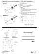
ASSEMBLY/WIRING INSTRUCTIONS
1 To remove plug or socket inserts for wiring, use cap assembly tool to
unscrew locking ring.
2 As appropriate to main body type, thread cable through component parts
as shown in the illustrations.
3 Strip insulation from cable as shown in Flex Mounting diagram.
4 2 to 7 pole inserts:
Insert bare wire ends into terminals on plug/socket insert and fully tighten
screws.
Note: If connector is to be used on mains voltage ensure that wires are
connected as shown below.
9 pole inserts:
Pins and sockets are supplied loose for pre-crimping. Crimping tools
(including hand versions) and a contact extraction device are available.
Please enquire.
12 and 25 pole inserts:
Pins and sockets are supplied loose for pre-crimping and pre-soldering.
Crimping tools (including hand version) and a contact extraction device are
available. Please enquire.
5 After connecting wires, draw cable back until plug/socket insert is correctly
seated in D shaped location in the main body. Screw home locking ring
using cap assembly tool.
6 For cable mounted units, slide gland cage and gland down cable and into
main body then screw gland nut fully home. It is essential to ensure that
the gland nut is fully tightened to ensure cable is securely sealed and
clamped. For panel, bulkhead and flange units correctly seat sealing
washer and main body onto mounting surface and screw down using rear
nut or screw/bolts with seals. Ensure seals and glands are kept clean.
Locking cap secures plug to socket.
Note:
To ensure that the correct sealing properties of the connector are achieved it is
imperative that all ‘O’ rings are correctly located and seated before assembly.
Please refer to the exploded diagrams for the locations of these seals.
Standard Buccaneer Waterproof Electrical Cable Connector
F
LEX MOUNTING
FRONT OF PANEL MOUNTING
REAR OF PANEL MOUNTING
LOW PROFILE FLANGE MOUNTING
BULKHEAD/SURFACE MOUNTING
Mains Wire Connections
Important - connect
wires Brown to terminal
L, Blue to terminal N
and Green/Yellow to
terminal E
For your protection all mains (250V)
e
quipment used out of doors, in damp or
wet conditions should be supplied from a
correctly fused source and protected by an
approved R.C.D. Eg: BS7071, BS7288,
BS4293, BSEN61008 or BSIEC1008.
IF IN DOUBT SEEK ADVICE
I
MPORTANT SAFETY NOTICE
FLEX MOUNTING IN-LINE
Part No: 13158, issue 8
W
iring and Assembly Instructions