
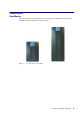
Specifications


17
NovaScale 4020 Quick Start Guide
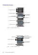
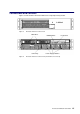
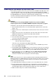
Figure 8 shows back panel switches, indicators and connectors.
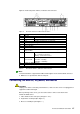
Figure 8. NovaScale 4020 Server Back Panel Features
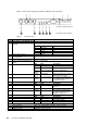
Item
Description
A PCI Slots
Slot 1 100 MHz, 64–bit PCI–X slot, full length
Slot 2 100 MHz, 64–bit PCI–X slot, full length
Slot 3 133 MHz, 64–bit PCI–X slot, full length
B Two AC input power connectors
C External SCSI connector
1
D System ID switch
E System ID LED (blue)
F Two LAN ports, RJ45 connector (LAN1 on bottom, LAN2 on top)
LAN port LEDs:
Green LED On – ethernet link is detected
Off – no ethernet connection
Blinking – ethernet link is active
Green/Amber
dual color LED
Ethernet speed indicator
Green On – 100 Mbps
Amber On – 1000 Mbps
G Serial port
2
, RJ45 connector
H Two USB 1.1 ports, 4–pin connectors (USB0 on bottom, USB1 on top)
I Video port, standard VGA compatible, 15–pin connector
Table 2. Back Panel Switches, Indicators and Connectors
Note:
1. External SCSI bus supports both LVDS and SE signals via the external SCSI connector.
2. EMP access is provided via shared serial port.
Connecting the Monitor, Keyboard, and Mouse
CAUTION:
Unplug server before connecting external devices, make sure the server is not plugged in or
equipment could be damaged.
Before powering on the server, you must connect these devices to the back of the
NovaScale 4020 Server.
1. Video monitor to the video port (I in Figure 7. or 8 )
2. Keyboard to a USB port (G in Figure 7. )
3. Mouse to a USB port (G in Figure 7. )