Installation and User's Guide REFERENCE 86 A1 51FA 00 NOVASCALE R422-E2/R422-INF-E2
NOVASCALE R422-E2/R422-INF-E2 Installation and User's Guide Hardware May 2009 BULL CEDOC 357 AVENUE PATTON B.P.
The following copyright notice protects this book under Copyright laws which prohibit such actions as, but not limited to, copying, distributing, modifying, and making derivative works. Copyright © Bull SAS 2009 Copyright © Super Micro Computer, Inc., 2009 Printed in France Suggestions and criticisms concerning the form, content, and presentation of this book are invited. A form is provided at the end of this book for this purpose.
Preface Preface About This Manual This manual is written for professional system integrators and PC technicians. It provides information for the installation and use of the NovaScale R422-E2/ R422-INF-E2. Installation and maintenance should be performed by experienced technicians only. The NovaScale R422-E2/R422-INF-E2 is a 1U Twin (two serverboards in a 1U chassis) rackmount server chassis and two R422-E2/R422-INF-E2 serverboards.
NovaScale R422-E2/R422-INF-E2 Installation and User's Guide Chapter 4: System Safety You should thoroughly familiarize yourself with this chapter for a general overview of safety precautions that should be followed when installing and servicing the NovaScale R422-E2/R422-INF-E2. Chapter 5: Advanced Serverboard Setup Chapter 5 provides detailed information on the R422-E2/R422-INF-E2 serverboard, including the locations and functions of connectors, headers and jumpers.
Preface Notes V
NovaScale R422-E2/R422-INF-E2 Installation and User's Guide VI
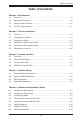
Table of Contents Table of Contents Chapter 1. Introduction 1-1 Overview.......................................................................................................... 1-1 1-2 Serverboard Features...................................................................................... 1-2 1-3 Server Chassis Features................................................................................. 1-5 1-4 1U Twin: System Notes....................................................................
NovaScale R422-E2/R422-INF-E2 Installation and User's Guide 5-9 Back Panel Connector Pin Definitions........................................................... 5-17 5-10 Front Control Panel........................................................................................ 5-22 5-11 Connecting Cables......................................................................................... 5-27 5-12 Jumper Settings.....................................................................................
Chapter 1: Introduction Chapter 1. Introduction 1-1 Overview The NovaScale R422-E2/R422-INF-E2 is a "1U Twin" server comprised of the 1U chassis and two (twin) R422-E2/R422-INF-E2 serverboards. Please refer to our web site for information on operating systems that have been certified for use with the NovaScale R422-E2/R422-INF-E2. In addition to the serverboard and chassis, various hardware components may have been included with the NovaScale R422-E2/R422-INF-E2, as listed below.
NovaScale R422-E2/R422-INF-E2 Installation and User's Guide 1-2 Serverboard Features At the heart of the NovaScale R422-E2/R422-INF-E2 lies two R422-E2/R422-INFE2 dual processor serverboards, which are based on Intel's 5520 chipset. Below are the main features of the NovaScale R422-E2/R422-INF-E2 serverboard. Note that the features on each board are doubled for the server.
Chapter 1: Introduction Ethernet Ports Two Intel® 82563EB network controllers are integrated into each of the serverboards to support a total of four Gigabit LAN ports (100/1000Base-T/1000BaseTX, RJ45 output). Onboard Controllers/Ports Onboard I/O backpanel ports include one COM port, a VGA port, two USB ports, two Gigabit LAN (NIC) ports and (on the NovaScale R422-INF-E2 only) an InfiniBand® (MT25204 controller) 20 Gbps port.
NovaScale R422-E2/R422-INF-E2 Installation and User's Guide Figure 1-1. Intel 5500 Chipset: System Block Diagram Note: This is a general block diagram. Please see Chapter 5 for details.
Chapter 1: Introduction 1-3 Server Chassis Features The following is a general outline of the main features of the 1U chassis. Details on the chassis can be found in Chapter 6. System Power The NovaScale R422-E2 chassis includes a single 980W cold-swap power supply, which provides the power to both serverboards housed in the chassis. SATA Subsystem The NovaScale R422-E2 chassis was designed to support four SATA hard drives, which are hot-swappable units.
NovaScale R422-E2/R422-INF-E2 Installation and User's Guide 1-4 1U Twin: System Notes As a 1U Twin configuration, the NovaScale R422-E2/R422-INF-E2 is a unique server system. With two system boards incorporated into a single chassis, there are several points you should keep in mind. System Power A single power supply is used to provide the power for both serverboards. Each serverboard however, can be shut down independently of the other with the power button on its own control panel.
Chapter 2: Server Installation Chapter 2. Server Installation 2-1 Overview This chapter provides a quick setup checklist to get your NovaScale R422-E2/ R422-INF-E2 up and running. Following these steps in the order given should enable you to have the system operational within a minimum amount of time. This quick setup assumes that your system has come to you with the processors and memory preinstalled. If your system is not already fully integrated with a serverboard, processors, system memory etc.
NovaScale R422-E2/R422-INF-E2 Installation and User's Guide • • This product is for installation only in a Restricted Access Location (dedicated equipment rooms, service closets and the like). This product is not suitable for use with visual display work place devices according to §2 of the the German Ordinance for Work with Visual Display Units.
Chapter 2: Server Installation • • Always keep the rack's front door and all panels and components on the servers closed when not servicing to maintain proper cooling. Make sure all power and data cables are properly connected and not blocking the chassis airflow. See Chapter 5 for details on cable connections.
NovaScale R422-E2/R422-INF-E2 Installation and User's Guide 2-4 Installing the System into a Rack This section provides information on installing the NovaScale R422-E2/R422-INFE2 into a rack unit with the rack rails provided. If the system has already been mounted into a rack, you can skip ahead to Sections 2-5 and 2-6. There are a variety of rack units on the market, which may mean the assembly procedure will differ slightly.
Chapter 2: Server Installation Figure 2-2. Identifying the Sections of the Rack Rails (right side rail shown) Figure 2-3.
NovaScale R422-E2/R422-INF-E2 Installation and User's Guide Installing the Inner Rail Extension The chassis includes a set of inner rails in two sections: inner rails and inner rail extensions. The inner rails are preattached and do not interfere with normal use of the chassis if you decide not to use a server rack. Attach the inner rail extension to stabilize the chassis within the rack. To install the inner rails: 1.
Chapter 2: Server Installation To install the outer rails of the rack: 1. Attach the short bracket to the outside of the long bracket. You must align the pins with the slides. Also, both bracket ends must face the same direction. 2. Adjust both the short and long brackets to the proper distance so that the rail fi ts snugly into the rack. 3. Secure the long bracket to the front side of the outer rail with two M5 screwsand the short bracket to the rear side of the outer rail with three M5 screws. 4.
NovaScale R422-E2/R422-INF-E2 Installation and User's Guide Installing the Server into the Rack You should now have rails attached to both the chassis and the rack unit. The next step is to install the server into the rack. Do this by lining up the rear of the chassis rails with the front of the rack rails. Slide the chassis rails into the rack rails, keeping the pressure even on both sides (you may have to depress the locking tabs when inserting). See Figure 2-5.
Chapter 2: Server Installation 2-5 Checking the Serverboard Setup After you install the NovaScale R422-E2/R422-INF-E2 in the rack, you will need to open the top cover to make sure the serverboard is properly installed and all the connections have been made. Accessing the Inside of the System 1. Release the retention screws that secure the system to the rack. 2. Grasp the two handles on either side and pull the system straight out until it locks (you will hear a "click"). 3.
NovaScale R422-E2/R422-INF-E2 Installation and User's Guide 2-6 Preparing to Power On Next, you should check to make sure the peripheral drives and the SATA drives and SATA backplane have been properly installed and all connections have been made. Checking the SATA drives 1. All drives are accessable from the front of the server. The SATA disk drives can be installed and removed from the front of the chassis without removing the top chassis cover. 2.
Chapter 2: Server Installation Figure 2-6.
NovaScale R422-E2/R422-INF-E2 Installation and User's Guide Notes 2-12
Chapter 3: System Interface Chapter 3. System Interface 3-1 Overview There are several LEDs on the two control panels as well as others on the SATA drive carriers to keep you constantly informed of the overall status of the system as well as the activity and health of specific components. There are also two buttons on each control panel. This chapter explains the meanings of all LED indicators and the appropriate response you may need to take.
NovaScale R422-E2/R422-INF-E2 Installation and User's Guide 3-3 Control Panel LEDs Each of the two control panels located on the front of the NovaScale R422-E2/ R422-INF-E2 chassis has five LEDs. Each LED provides you with critical information related its own specific serverboard. This section explains what each LED indicates when illuminated and any corrective action you may need to take. Overheat/Fan Fail When this LED flashes, it indicates a fan failure.
Chapter 3: System Interface Power Indicates power is being supplied to the system's power supply unit. This LED should normally be illuminated when the system is operating. 3-4 SATA Drive Carrier LEDs Each SATA drive carrier has two LEDs. • • Green: When illuminated, the green LED on the front of the SATA drive carrier indicates drive activity. A connection to the SATA backplane enables this LED to blink on and off when that particular drive is being accessed.
NovaScale R422-E2/R422-INF-E2 Installation and User's Guide Notes 3-4
Chapter 4: System Safety Chapter 4. System Safety 4-1 Electrical Safety Precautions ! Basic electrical safety precautions should be followed to protect yourself from harm and the NovaScale R422-E2/R422-INF-E2 from damage: • • • • • • • Be aware of the locations of the power on/off switch on the chassis as well as the room's emergency power-off switch, disconnection switch or electrical outlet. If an electrical accident occurs, you can then quickly remove power from the system.
NovaScale R422-E2/R422-INF-E2 Installation and User's Guide • Serverboard Battery: CAUTION - There is a danger of explosion if the onboard battery is installed upside down, which will reverse its polarites (see Figure 4-1). This battery must be replaced only with the same or an equivalent type recommended by the manufacturer. Dispose of used batteries according to the manufacturer's instructions.
Chapter 4: System Safety 4-3 ESD Precautions ! Electrostatic discharge (ESD) is generated by two objects with different electrical charges coming into contact with each other. An electrical discharge is created to neutralize this difference, which can damage electronic components and printed circuit boards.
NovaScale R422-E2/R422-INF-E2 Installation and User's Guide 4-4 Operating Precautions ! Care must be taken to assure that the chassis cover is in place when the NovaScale R422-E2/R422-INF-E2 is operating to assure proper cooling. Out of warranty damage to the system can occur if this practice is not strictly followed. Figure 4-1.
Chapter 5: Advanced Serverboard Setup Chapter 5. Advanced Serverboard Setup This chapter covers the steps required to install the NovaScale R422-E2/R422INF-E2 serverboard into the chassis, connect the data and power cables and install add-on cards. All serverboard jumpers and connections are also described. A layout and quick reference chart are included in this chapter for your reference.
NovaScale R422-E2/R422-INF-E2 Installation and User's Guide Unpacking The serverboard is shipped in antistatic packaging to avoid electrostatic discharge. When unpacking the board, make sure the person handling it is static protected. 5-2 Installing the Serverboard This section explains the first step of physically mounting the serverboard into the chassis. Following the steps in the order given will eliminate the most common problems encountered in such an installation.
Chapter 5: Advanced Serverboard Setup 5-3 Connecting Cables Now that the serverboards are installed, the next step is to connect the cables to the boards. These include the data cables for the peripherals and control panel and the power cables. Connecting Data Cables The cables used to transfer data from the peripheral devices have been carefully routed to prevent them from blocking the flow of cooling air that moves through the system from front to back.
NovaScale R422-E2/R422-INF-E2 Installation and User's Guide Connecting the Control Panel JF1 contains header pins for various front control panel connectors. See Figure 5-1 for the pin locations of the various front control panel buttons and LED indicators. All JF1 wires have been bundled into a single ribbon cable to simplify this connection. Make sure the red wire plugs into pin 1 as marked on the board.
Chapter 5: Advanced Serverboard Setup 5-4 Control Panel Connectors/IO Ports The I/O ports are color coded in conformance with the PC 99 specifi cation. See the picture below for the colors and locations of the various I/O ports. Figure 5-2. Back Panel Connectors/IO Ports 1. USB 0 2. USB 1 3 IPMI_dedicated LAN (R422-E2/ R422-INF-E2) 4. LAN 1 5. LAN 2 6. COM Port 1 (Black) 7. VGA (Blue) 8. Infiniband (R422-INF-E2) 9.
NovaScale R422-E2/R422-INF-E2 Installation and User's Guide 5-5 Installing Processor and Heat Sink ! When handling the processor package, avoid placing direct pressure on the label area of the fan. Notes: 1. Always connect the power cord last and always remove it before adding, removing or changing any hardware components. Make sure that you install the processor into the CPU socket before you install the CPU heatsink. 2.
Chapter 5: Advanced Serverboard Setup CPU 4. After removing the plastic cap, using your thumb and the index finger , hold the CPU at the north and south CPU Socket center edges. Socket keys 5. Align the CPU key, the semi-circle cutout, against the socket key, the notch below the gold color dot on the side of the socket. 6. Once both the CPU and the socket are aligned, carefully lower the CPU straight down into the socket.
NovaScale R422-E2/R422-INF-E2 Installation and User's Guide Installing a CPU Heatsink 1. Do not apply any thermal grease to the heatsink or the CPU die because the required amount has already been applied. Screw #2 Screw #1 2. Place the heatsink on top of the CPU so that the four mounting holes are aligned with those on the retention mechanism. Screw #1 Install Screw #1 3.
Chapter 5: Advanced Serverboard Setup Removing the Heatsink ! Warning: We do not recommend that the CPU or the heatsink be removed. However, if you do need to remove the heatsink, please follow the instructions below to uninstall the heatsink and prevent damage to the CPU or other components. 1. Unplug the power cord from the power supply. 2. Disconnect the heatsink fan wires from the CPU fan header. 3.
NovaScale R422-E2/R422-INF-E2 Installation and User's Guide 5-6 Installing Memory CAUTION Exercise extreme care when installing or removing DIMM modules to prevent any possible damage. Also note that the memory is interleaved to improve performance (See step 1). Installing a DIMM 1. Insert the desired number of DIMMs into the memory slots, starting with P1-DIMM 1A.
Chapter 5: Advanced Serverboard Setup Memory Support The R422-E2/R422-INF-E2 supports up to 48 GB Registered ECC DDR3 1333 MHz/1066 MHz/800 MHz in 12 DIMMs (w/maximum of 8 GB per DIMM). Also, memory speed support is dependent on the type of CPU used on the board. DIMM Module Population Configuration For memory to work properly, follow the tables below for memory installation: DIMM Population Table DIMM Slots per Channel DIMMS Populated per Channel DIMM Type Reg.
NovaScale R422-E2/R422-INF-E2 Installation and User's Guide Installing and Removing DIMMs To install: Insert module vertically and press down until it snaps into place. Pay attention to the alignment notch at the bottom. To Remove: Use your thumbs to gently push the release tabs near both ends of the module. This should release it from the slot. Figure 5-3.
Chapter 5: Advanced Serverboard Setup 5-7 Adding PCI Cards PCI-Express 2.0 Slot The NovaScale R422-E2/R422-INF-E2 includes two preinstalled riser cards. These riser cards support two low-profile PCI-Express 2.0 (second generation PCI-E) cards to fit inside the chassis. PCI Card Installation The riser card has already been preinstalled into the serverboard. Perform the following steps to add a PCI add-on card: 1. Remove the PCI slot shield on the chassis by releasing the locking tab. 2.
NovaScale R422-E2/R422-INF-E2 Installation and User's Guide 5-8 Serverboard Details Figure 5-4.
Chapter 5: Advanced Serverboard Setup NovaScale R422-E2/R422-INF-E2 Serverboard Quick Reference Jumper Description Default Setting JBT1 CMOS Clear (See page 5-34) JPEN1 Normal Power Enable* Pins 1-2 (Enabled) JPG1 VGA Enable Pins 1-2 (Enabled) JPL1 LAN1/2 Enable Pins 1-2 (Enabled) J_UID_OW Red LED OW (Pins 7/8 of JF1) (see page 5-36) Off (Overwrites) JWD Watch Dog Pins 1-2 (Reset) * To use Hot-swap support on the 827 chassis, connect a cable to pins 2~3 on JPEN1.
NovaScale R422-E2/R422-INF-E2 Installation and User's Guide T-SGPIO-0/T-SGPIO-1 Serial General Purpose Input/Output Headers USB0/1 Universal Serial Bus (USB) Ports 0/1, 2/3 VGA Video Port LED Description LE2 Onboard Standby PWR warning LED Indicator ! Warning: To avoid possible system overheating, please be sure to provide adequate airflow to your system.
Chapter 5: Advanced Serverboard Setup 5-9 Back Panel Connector Pin Definitions Universal Serial Bus (USB) Back Panel USB 0/1 Pin Definitions Two Universal Serial Bus ports (USB 0/1) are located on the I/O back panel. Additional two USB connections (USB 2/3) are used to provide front chassis access. Connect USB cables to these USB ports/headers to use USB connections. (USB cables are not included). See the tables on the right for pin definitions.
NovaScale R422-E2/R422-INF-E2 Installation and User's Guide Ethernet Ports LAN Ports Pin Definitions Two Ethernet ports are located next to the USB 0/1 on the IO Backplane. In addition, an IPMI Dedicated LAN is located above the USB ports 0/1. These ports accept RJ45 type cables. Notes: 1. The IPMI Dedicated LAN is for R22-E2/R422-INF-E2) 2. Please refer to the LED Indicator Section for LAN LED information.
Chapter 5: Advanced Serverboard Setup Serial Ports Serial Ports Pin Definitions (COM1) A COM Port is located on the IO Backplane. See the table on the right for pin definitions.. Pin # Definition Pin # Definition 1 CDC 6 DSR 2 RXD 7 RTS 3 TXD 8 CTS 4 DTR 9 RI 5 Ground 10 NC NC: No Connection Video Connector A Video (VGA) connector is located next to the COM Port on the IO backplane. This connector is used to provide video and CRT display.
NovaScale R422-E2/R422-INF-E2 Installation and User's Guide InfiniBand Connecttion (R422-INF-E2) InfiniBand Pin Definitions The onboard InfiniBand connector is located on the backplane on the motherboard. This switch is primarily used for High-performance computing. See the table on the right for pin definitions..
Chapter 5: Advanced Serverboard Setup Unit Identifier Switches UID Switch Two Unit Identifier (UID) Switches and LED Indicators are located on the motherboard. The Front Panel UID Switch is located at Pin 13 on the Front Control Panel (JF1). The Rear UID Switch is located at SW1 next to the Infi niBand Connector. The Front Panel UID LED is located at Pin 7 of JF1, and the Rear UID LED is located at LE4.
NovaScale R422-E2/R422-INF-E2 Installation and User's Guide 5-10 Front Control Panel JF1 contains header pins for various buttons and indicators that are normally located on a control panel at the front of the chassis. These connectors are designed specifi cally for use with Supermicro server chassis. See the figure below for the descriptions of the various control panel buttons and LED indicators. Refer to the following section for descriptions and pin definitions.
Chapter 5: Advanced Serverboard Setup Front Control Panel Pin Definitions Power LED The Power LED connection is located on pins 15 and 16 of JF1. Refer to the table on the right for pin definitions. Power LED Pin Definitions (JF1) Pin# Definition 15 +3.3V SB 16 PWR LED HDD/FP UID Switch The HDD/UID Switch connections are located on pins 13/14 of JF1. Attach a hard-drive LED cable to display HDD or SATA activities. This connection can also be used as a front panel UID (Unit Identifi er) switch.
NovaScale R422-E2/R422-INF-E2 Installation and User's Guide NIC1 LED Indicator The NIC (Network Interface Controller) LED connections for GLAN port 1 are located on pins 11 and 12 of JF1. Attach a NIC LED cable to display LAN Port1 connections and activities. Refer to the table on the right for pin definitions. NIC2 LED Indicator The Network LED connections for GLAN port 2 are located on pins 9 and 10 of JF1. Attach a NIC LED cable to display LAN Port2 connections and activities.
Chapter 5: Advanced Serverboard Setup Overheat (OH)/Fan Fail/UID LED Connect an LED cable to pins 7 and 8 of JF1 to use the Overheat/Fan Fail/Power Fail and UID LED connections. The Red LED on pin 8 provides warnings of an overheat, fan failure or power failure. The Blue LED on pin 7 works as the UID LED indicator for the front panel UID switch located on pins 13~14 of JF1. When Jumper J_UID_OW is set to off (default), the Red LED takes precedence over the Blue LED.
NovaScale R422-E2/R422-INF-E2 Installation and User's Guide Reset Button The Reset Button connection is located on pins 3 and 4 of JF1. Attach it to a hardware reset switch on the computer case. Refer to the table on the right for pin definitions. Reset Button Pin Definitions (JF1) Pin# Definition 3 Reset 4 Ground Power Button The Power Button connection is located on pins 1 and 2 of JF1. Momentarily contacting both pins will power on/off the system.
Chapter 5: Advanced Serverboard Setup 5-11 Connecting Cables. 20-pin Proprietary Power Connectors There are two 20-pin main power supply connectors (PWR1, PWR2) and a 4-pin auxiliary power connector (JP10) on the motherboard. These power connectors meet the SSI EPS 12V specification. For power supply to work properly, please follow the instructions given below. See the table on the right for pin definitions. Also refer to the layout below for the PWR connector locations.
NovaScale R422-E2/R422-INF-E2 Installation and User's Guide 4-pin Auxiliary Power Connector 4-pin Power Pin Definitions In addition to two 20-pin power connectors, a 4-pin 12V PWR supply is located at JP10 on the motherboard. This power connector is used to provide power supply to hard drive disks. Refer to the layout below for the location. Note 1: The 4-pin Auxiliary Power Connector is used for power supply output to HDDs only.
Chapter 5: Advanced Serverboard Setup Fan Headers Fan Header Pin Definitions The R422-E2/R422-INF-E2 has four chassis/system fan headers (Fan1 to Fan4) on the motherboard. All these 4-pin fans headers are backward compatible with the traditional 3-pin fans. 3-pin fans do not support fan speed control. However, fan speed control is available for 4-pin fans. The fan speeds are controlled by Thermal Management via Hardware Monitoring in the Advanced Setting in the BIOS. (The Default setting is Disabled.
NovaScale R422-E2/R422-INF-E2 Installation and User's Guide NMI Header The non-maskable interrupt header is located at JNMI1. Refer to the table on the right for pin definitions. NMI Button Pin Definitions (JF1) Pin# Definition 1 Control 2 Ground Internal Buzzer The Internal Buzzer, located at JSPK1, can be used to provide audible alarms for various beep codes. See the table on the right for pin defi nitions. Refer to the layout below for the locations of the Internal Speaker/ Buzzer.
Chapter 5: Advanced Serverboard Setup Wake-on-LAN Wake-on-Lan Pin Definitions The Wake-On-LAN header is located at JWOL1 on the motherboard. You must also have a LAN card with a Wake-On-LAN connector and a cable to use this feature. See the table on the right for pin definitions.
NovaScale R422-E2/R422-INF-E2 Installation and User's Guide SMB (I²C) Connector PWR SMB Pin Definitions System Management Bus (I2C) Connector (J18) monitors power supply, fan and system temperatures. See the table on the right for pin definitions. IPMB I²C SMB Pin# Definition 1 Clock 2 Data 3 PWR Fail 4 Ground SMB Header Pin Definitions A System Management Bus header for the IPMI slot is located at IPMB. Connect the appropriate cable here to use the IPMB I²C connection on your system.
Chapter 5: Advanced Serverboard Setup 5-12 Jumper Settings Explanation of Jumpers To modify the operation of the motherboard, jumpers can be used to choose between optional settings. Jumpers create shorts between two pins to change the function of the connector. Pin 1 is identifi ed with a square solder pad on the printed circuit board. See the motherboard layout pages for jumper locations. Note: On two pin jumpers, "Closed" means the jumper is on and "Open" means the jumper is off the pins.
NovaScale R422-E2/R422-INF-E2 Installation and User's Guide CMOS Clear JBT1 is used to clear CMOS. Instead of pins, this "jumper" consists of contact pads to prevent the accidental clearing of CMOS. To clear CMOS, use a metal object such as a small screwdriver to touch both pads at the same time to short the connection. Always remove the AC power cord from the system before clearing CMOS.
Chapter 5: Advanced Serverboard Setup Power Setting Select JPEN1 allows you to confi gure power settings for hot-swap support on the Hot-Swap version of Chassis 827. To enable hot-swap support for this model of chassis, connect a cable to Pins 2~3 of JPEN1. To use the regular power setting for other chassis, close Pins 1~2 on JPEN1 with a cap. See the table on the right for jumper settings. VGA Enable JPG1 allows you to enable or disable the onboard VGA connection supported by the onboard VGA Controller.
NovaScale R422-E2/R422-INF-E2 Installation and User's Guide J_UID_OW (-Overwriting) When the jumper J_UID_OW is set to Off (default), the Red LED (Overheat/Fan Fail/PWR Fail/UID LED) located on Pin 8 of the Front Control Panel (JF1) will take precedence over the Blue UID_LED located on Pin 7 of JF1. In this case, when the Red LED is on, the Blue LED will be turned off. When the RED LED is off, the Blue UID_LED can be on or off.
Chapter 5: Advanced Serverboard Setup 5-13 Onboard Indicators LAN1/LAN2 LEDs There are two GLAN ports on the motherboard. An additional IPMI dedicated LAN port is also located on the R422-E2/R422-INF-E2. Each Gigabit Ethernet LAN port has two LEDs. The yellow LED indicates activity, while the Link LED may be green, amber or off to indicate the speed of the connection. See the tables at right for more information. Note: IPMI dedicated LAN does not operate at 1 Gbps.
NovaScale R422-E2/R422-INF-E2 Installation and User's Guide InfiniBand LED Indicators (LEB1/LEB2) InfiniBand Link LED (LEB1) Settings Two Infi niBand LED Indicators (LEB1/LEB2) are located on the motherboard. The green LED (LEB1) is the Infi niBand Link LED. The yellow LED (LEB2) indicates activity. Refer to the table on the right for details. Also see the layout below for the LED locations. Onboard Power LED An Onboard Power LED is located at LE2 on the motherboard.
Chapter 5: Advanced Serverboard Setup 5-14 Serial ATA and PCI-E Connections Serial ATA Ports Six Serial ATA Ports (I-SATA0~I-SATA 5) are located at JS1~JS6 on the motherboard. These ports provide serial-link signal transmission, which is faster than that of the traditional Parallel ATA. See the table on the right for pin definitions.. PCI-Express x16 Gen. 2 Slot Serial ATA Pin Definitions Pin# Definition 1 Ground 2 TX_P 34 TX_N 5 Ground 6 RX_N 7 RX_P 8 Ground A PCI-Express x16 (Gen.
NovaScale R422-E2/R422-INF-E2 Installation and User's Guide Notes 5-40
Chapter 6: Advanced Chassis Setup Chapter 6. Advanced Chassis Setup This chapter covers the steps required to install components and perform maintenance on the NovaScale R422-E2 chassis. For component installation, follow the steps in the order given to eliminate the most common problems encountered. If some steps are unnecessary, skip ahead to the step that follows. The only tool you will need to install components and perform maintenance is a Philips screwdriver.
NovaScale R422-E2/R422-INF-E2 Installation and User's Guide Figure 6-1. Chassis Front View Control Panel: Primary Serverboard Control Panel: Secondary Serverboard SATA Drives Figure 6-2. Chassis Rear View LAN Ports PCI-Express x16 Slot Power Supply LAN Ports PCI-Express x16 Slot USB Ports COM Port VGA Port InfiniBand Port* USB Ports COM Port VGA Port InfiniBand Port* *The InfiniBand ports are included on the NovaScale R422-INF-E2 only.
Chapter 6: Advanced Chassis Setup 6-3 System Fans Each serverboard has its own set of three 4-cm high-performance fans (for a total of six in the chassis) to provide the cooling for the NovaScale R422-E2/R422-INF-E2. Fan speed may be controlled by a setting in BIOS (see Chapter 7). System Fan Failure If a fan fails, the remaining fans will ramp up to full speed and the overheat/fan fail LED on the control panel will blink on and off.
NovaScale R422-E2/R422-INF-E2 Installation and User's Guide Figure 6-3. Mounting a Drive in a Carrier Installing/Removing Hot-swap SATA Drives 1. To remove a carrier, push the release button located beside the drive LEDs. 2. Swing the handle fully out and use it to pull the unit straight out (see Figure 6-4). Figure 6-4.
Chapter 6: Advanced Chassis Setup 6-5 Power Supply The NovaScale R422-E2/R422-INF-E2 has a single 980 watt power supply. This power supply has the capability of operating at 100 - 240 input volts. Depress both main power buttons on the front of the chassis and then unplug the AC power cord to completely remove power from the system before removing the power supply. Power Supply Failure If the power supply unit fails, the system will shut down and you will need to replace the power supply unit.
NovaScale R422-E2/R422-INF-E2 Installation and User's Guide Installing a New Power Supply 1. Replace the failed unit with the exact same power supply model. 2. Carefully insert the new unit into position in the chassis and secure it with the two screws at the rear of the unit. 3. Before reconnecting the power cord, make sure the power switch on the power supply is in the off position. 4. Reconnect the power cord, replace the chassis top cover and push the unit back into the rack. 5.
Chapter 7: BIOS Chapter 7. BIOS 7-1 Introduction This chapter describes the AMI BIOS Setup Utility for the R422-E2/R422INF-E2. The AMI ROM BIOS is stored in a Flash EEPROM and can be easily updated. This chapter describes the basic navigation of the AMI BIOS Setup Utility setup screens. Starting BIOS Setup Utility To enter the AMI BIOS Setup Utility screens, press the key while the system is booting up. Note: In most cases, the key is used to invoke the AMI BIOS setup screen.
NovaScale R422-E2/R422-INF-E2 Installation and User's Guide Starting the Setup Utility Normally, the only visible Power-On Self-Test (POST) routine is the memory test. As the memory is being tested, press the key to enter the main menu of the AMI BIOS Setup Utility. From the main menu, you can access the other setup screens. An AMI BIOS identification string is displayed at the left bottom corner of the screen below the copyright message.
Chapter 7: BIOS System Overview The following BIOS information will be displayed: System Time/System Date Use this option to change the system time and date. Highlight System Time or System Date using the arrow keys. Key in new values through the keyboard and press . Press the key to move between fields. The date must be entered in Day MM/DD/YY format. The time is entered in HH:MM:SS format. (Note: The time is in the 24-hour format. For example, 5:30 P.M. appears as 17:30:00.
NovaScale R422-E2/R422-INF-E2 Installation and User's Guide 7-3 Advanced Setup Configurations Use the arrow keys to select Boot Setup and hit to access the submenu items: Boot Features Access the submenu to make changes to the following settings. QuickBoot Mode If Enabled, this option will skip certain tests during POST to reduce the time needed for system boot. The options are Enabled and Disabled.
Chapter 7: BIOS Wait For 'F1' If Error This forces the system to wait until the 'F1' key is pressed if an error occurs. The options are Disabled and Enabled. Hit 'Del' Message Display This feature displays "Press DEL to run Setup" during POST. The options are Enabled and Disabled. Interrupt 19 Capture Interrupt 19 is the software interrupt that handles the boot disk function.
NovaScale R422-E2/R422-INF-E2 Installation and User's Guide Processor and Clock Options This submenu allows the user to configure the Processor and Clock settings. Ratio CMOS Setting This option allows the user to set the ratio between the CPU Core Clock and the Memory Frequency. (Note: if an invalid ratio is entered, the AMI BIOS will restore the setting to the previous state.) The default setting depends on the type of CPU installed on the motherboard.
Chapter 7: BIOS Simultaneous Multi-Threading (Available when supported by the CPU) Set to Enabled to use the Simultaneous Multi-Threading Technology, which will result in increased CPU performance. The options are Disabled and Enabled. Active Processor Cores Set to Enabled to use a processor's Second Core and beyond. (Please refer to Intel's web site for more information.) The options are All, 1 and 2.
NovaScale R422-E2/R422-INF-E2 Installation and User's Guide Advanced Chipset Control The items included in the Advanced Settings submenu are listed below: CPU Bridge Configuration QPI Links Speed This feature selects QPI's data transfer speed. The options are Slow-mode, and Full Speed. QPI Frequency This selects the desired QPI frequency. The options are Auto, 4.800 GT, 5.866GT, 6.400 GT. QPI L0s and L1 This enables the QPI power state to low power.
Chapter 7: BIOS Patrol Scrubbing A memory error-correction scheme that works in the background looking for and correcting resident errors. The options are Enabled and Disabled. Throttling - Closed Loop/Throttling - Open Loop Throttling improves reliability and reduces power in the processor by automatic voltage control during processor idle states. Available options are Disabled and Enabled.
NovaScale R422-E2/R422-INF-E2 Installation and User's Guide North Bridge Configuration This feature allows the user to configure the settings for the Intel North Bridge chip. Crystal Beach/DMA (Direct Memory Access) This feature works with the Intel I/O AT (Acceleration Technology) to accelerate the performance of TOE devices. (Note: A TOE device is a specialized, dedicated processor that is installed on an add-on card or a network card to handle some or all packet processing of this add-on card.
Chapter 7: BIOS South Bridge Configuration This feature allows the user to configure the settings for the Intel ICH South Bridge chipset. USB Functions This feature allows the user to decide the number of onboard USB ports to be enabled. The Options are: Disabled, 2 USB ports, 4 USB ports, 6 USB ports, 8 Ports, 10 Ports and 12 USB ports. Legacy USB Support Select Enabled to use Legacy USB devices.
NovaScale R422-E2/R422-INF-E2 Installation and User's Guide IDE/SATA/Floppy Configuration When this submenu is selected, the AMI BIOS automatically detects the presence of the IDE devices and displays the following items: SATA#1 Configuration If Compatible is selected, it sets SATA#1 to legacy compatibility mode, while selecting Enhanced sets SATA#1 to native SATA mode. The options are Disabled, Compatible and Enhanced. Configure SATA#1 as This feature allows the user to select the drive type for SATA#1.
Chapter 7: BIOS Primary IDE Master/Slave, Secondary IDE Master/Slave, Third IDE Master, and Fourth IDE Master These settings allow the user to set the parameters of Primary IDE Master/ Slave, Secondary IDE Master/Slave, Third and Fourth IDE Master slots. Hit to activate the following submenu screen for detailed options of these items. Set the correct configurations accordingly. The items included in the submenu are: Type Select the type of device connected to the system.
NovaScale R422-E2/R422-INF-E2 Installation and User's Guide DMA Mode Select Auto to allow the BIOS to automatically detect IDE DMA mode when the IDE disk drive support cannot be determined. Select SWDMA0 to allow the BIOS to use Single Word DMA mode 0. It has a data transfer rate of 2.1 MBs. Select SWDMA1 to allow the BIOS to use Single Word DMA mode 1. It has a data transfer rate of 4.2 MBs. Select SWDMA2 to allow the BIOS to use Single Word DMA mode 2. It has a data transfer rate of 8.3 MBs.
Chapter 7: BIOS IDE Detect Timeout (sec) Use this feature to set the time-out value for the BIOS to detect the ATA, ATAPI devices installed in the system. The options are 0 (sec), 5, 10, 15, 20, 25, 30, and 35. PCI/PnP Configuration Clear NVRAM This feature clears the NVRAM during system boot. The options are No and Yes. Plug & Play OS Selecting Yes allows the OS to configure Plug & Play devices. (This is not required for system boot if your system has an OS that supports Plug & Play.
NovaScale R422-E2/R422-INF-E2 Installation and User's Guide Remote Access Configuration Remote Access This allows the user to enable the Remote Access feature. The options are Disabled and Enabled. If Remote Access is set to Enabled, the following items will display: Serial Port Number This feature allows the user decide which serial port to be used for Console Redirection. The options are COM 1 and COM 2. Serial Port Mode This feature allows the user to set the serial port mode for Console Redirection.
Chapter 7: BIOS Hardware Health Monitor This feature allows the user to monitor system health and review the status of each item as displayed. CPU Overheat Alarm This option allows the user to select the CPU Overheat Alarm setting which determines when the CPU OH alarm will be activated to provide warning of possible CPU overheat. Warning: 1.Any temperature that exceeds the CPU threshold temperature predefined by the CPU manufacturer may result in CPU overheat or system instability.
NovaScale R422-E2/R422-INF-E2 Installation and User's Guide can now send information to the motherboard what its ‘Temperature Tolerance’ is, and not the other way around. This results in better CPU thermal management. Bull has leveraged this feature by assigning a temperature status to certain thermal conditions in the processor (Low, Medium and High). This makes it easier for the user to understand the CPU’s temperature status, rather than by just simply seeing a temperature reading (i.e., 25° C).
Chapter 7: BIOS Fan1 ~ Fan 4 Reading This feature displays the fan speed readings from fan interfaces Fan1 through Fan5. Voltage Readings The following items will be monitored and displayed: CPU1 Vcore, CPU2 Vcore, +5Vin, +12Vcc (V), VP1 DIMM, VP2 DIMM, 3.3Vcc (V), and Battery Voltage ACPI Configuration Use this feature to configure Advanced Configuration and Power Interface (ACPI) power management settings for your system. ACPI Version Features The options are ACPI v1.0, ACPI v2.0 and ACPI v3.0.
NovaScale R422-E2/R422-INF-E2 Installation and User's Guide IPMI Configuration Intelligent Platform Management Interface (IPMI) is a set of common interfaces that IT administrators can use to monitor system health and to manage the system as a whole. For more information on the IPMI specifications, please visit Intel's website at www.intel.com. Status of BMC Baseboard Management Controller (BMC) manages the interface between system management software and platform hardware.
Chapter 7: BIOS View BMC System Event Log This feature displays the BMC System Event Log (SEL). It shows the total number of entries of BMC System Events. To view an event, select an Entry Number and pressing to display the information as shown in the screen.. • Total Number of Entries • SEL Entry Number • SEL Record ID • SEL Record Type • Timestamp, Generator ID • Event Message Format User • Event Sensor Type • Event Sensor Number, • Event Dir Type • Event Data.
NovaScale R422-E2/R422-INF-E2 Installation and User's Guide Set LAN Configuration Set this feature to configure the IPMI LAN adapter with a network address as shown in the following graphics.. Channel Number - Enter the channel number for the SET LAN Config command. This is initially set to [1]. Press "+" or "-" on your keyboard to change the Channel Number.
Chapter 7: BIOS IP Address Configuration Enter the IP address for this machine. This should be in decimal and in dotted quad form (i.e., 192.168.10.253). The value of each three-digit number separated by dots should not exceed 255 as shown in the screen below.. Parameter Selector Use this feature to select the parameter of your IP Address configuration. IP Address Current IP Address in BMC This item displays the current IP address used for your IPMI connection..
NovaScale R422-E2/R422-INF-E2 Installation and User's Guide MAC Address Configuration Parameter Selector Use this feature to select the parameter of your Mac Address configuration. Mac Address The BIOS will automatically enter the Mac address of this machine; however it may be over-ridden. Mac addresses are 6 two-digit hexadecimal numbers (Base 16, 0 ~ 9, A, B, C, D, E, F) separated by dots. (i.e., 00.30.48.D0.D4.60).
Chapter 7: BIOS Set PEF Configuration Set this feature to configure the Platform Event Filter (PEF). PEF interprets BMC events and performs actions based on pre-determined settings or 'traps' under IPMI 1.5 specifications. For example, powering the system down or sending an alert when a triggering event is detected. The following will appear if PEF Support is set to Enabled. The default is Disabled. PEF Action Global Control - These are the different actions based on BMC events.
NovaScale R422-E2/R422-INF-E2 Installation and User's Guide DMI Event Log View Event Log Use this option to view the System Event Log. Mark all events as read This option marks all events as read. The options are OK and Cancel. Clear event log This option clears the Event Log memory of all messages. The options are OK and Cancel. 7-4 Security Settings The AMI BIOS provides a Supervisor and a User password. If you use both passwords, the Supervisor password must be set first.
Chapter 7: BIOS User Access Level (Available when Supervisor Password is set as above) Available options are Full Access: grants full User read and write access to the Setup Utility, View Only: allows access to the Setup Utility but the fields cannot be changed, Limited: allows only limited fields to be changed such as Date and Time, No Access: prevents User access to the Setup Utility. Change User Password Select this feature and press to access the submenu , and then type in a new User Password.
NovaScale R422-E2/R422-INF-E2 Installation and User's Guide Boot Device Priority This feature allows the user to specify the sequence of priority for the Boot Device. The settings are 1st boot device, 2nd boot device, 3rd boot device, 4th boot device, 5th boot device and Disabled. • 1st Boot Device - [USB: XXXXXXXXX] • 2nd Boot Device - [CD/DVD: XXXXXXXXX] Hard Disk Drives This feature allows the user to specify the boot sequence from all available hard disk drives.
Chapter 7: BIOS 7-6 Exit Options Select the Exit tab from the AMI BIOS Setup Utility screen to enter the Exit BIOS Setup screen. Save Changes and Exit When you have completed the system configuration changes, select this option to leave the BIOS Setup Utility and reboot the computer, so the new system configuration parameters can take effect. Select Save Changes and Exit from the Exit menu and press .
NovaScale R422-E2/R422-INF-E2 Installation and User's Guide Notes 7-30
Appendix A: BIOS POST Messages Appendix A. BIOS Error Beep Codes During the POST (Power-On Self-Test) routines, which are performed each time the system is powered on, errors may occur. Non-fatal errors are those which, in most cases, allow the system to continue the boot-up process. The error messages normally appear on the screen. Fatal errors are those which will not allow the system to continue the boot-up procedure.
NovaScale R422-E2/R422-INF-E2 Installation and User's Guide Notes A-2
Appendix B: Intel HostRAID Setup Guidelines Appendix B. Intel HostRAID Setup Guidelines After all the hardware has been installed, you must first configure Intel's IOH-36D SATA RAID before you install the Windows Operating System and other software drivers.
NovaScale R422-E2/R422-INF-E2 Installation and User's Guide The Intel HostRAID Configurations The following RAID levels are supported: RAID 0 (Data Striping): this writes data in parallel, interleaved ("striped") sections of two hard drives. Data transfer rate is doubled over using a single disk. RAID1 (Data Mirroring): an identical data image from one drive is copied to another drive. The second drive must be the same size or larger than the first drive.
Appendix B: Intel HostRAID Setup Guidelines 8. During the system boot-up, press the and keys simultaneously to run the Intel RAID Configuration Utility when prompted by the following message: Press for the Intel RAID Configuration Utility. Note: The Intel RAID Configuration Utility is only available for systems with two or more drives installed. The Intel RAID Utility screen will not display in systems with one drive installed.
NovaScale R422-E2/R422-INF-E2 Installation and User's Guide Creating a RAID 0 Volume a. Select "Create RAID Volume" from the main menu and press the key. The following screen will appear: b. Specify a name for the RAID 0 set and press the key or the key to go to the next field. (You can use the key to select the previous menu.) c. When RAID Level item is highlighted, press the , keys to select RAID 0 (Stripe) and hit . d.
Appendix B: Intel HostRAID Setup Guidelines Creating a RAID 1 Volume a. Select "Create RAID Volume" from the main menu and press the key. The following screen will appear: b. Specify a name for the RAID 1 set and press the key or the key to go to the next field. (You can use the key to select the previous menu.) c. When RAID Level item is highlighted, press the , keys to select RAID 1 (Mirror) and hit . d.
NovaScale R422-E2/R422-INF-E2 Installation and User's Guide Creating a RAID 10 (RAID 1+ RAID 0) a. Select "Create RAID Volume" from the main menu and press the key. The following screen will appear: b. Specify a name for the RAID 10 set and press . c. When RAID Level item is highlighted, use the , keys to select RAID 10 (RAID1 + RAID0) and hit . d.
Appendix B: Intel HostRAID Setup Guidelines Creating a RAID 5 Set (Parity) a. Select "Create RAID Volume" from the main menu and press the key. The following screen will appear: b. Specify a name for the RAID 5 set and press . c. When the Raid Level is highlighted, use the , keys to select RAID 5 (Parity) and hit . d. When the Disk item is highlighted, press to select the HDD to configure as RAID.
NovaScale R422-E2/R422-INF-E2 Installation and User's Guide i. When asked "Are you sure you want to create this volume (Y/N), press "Y" to create the RAID volume, or type "N" to go back to the Create Volume menu. Deleting a RAID Volume ! Warning: Make sure you back up your data before deleting a RAID set. You will lose all data on the disk drives when deleting a RAID set. a. From the main menu, select item2-Delete RAID Volume, and press . b.
Appendix B: Intel HostRAID Setup Guidelines Resetting to Non-RAID and Resetting a RAID HDD Warning: Be cautious when you reset a RAID volume HDD to non-RAID ! or Resetting a RAID HDD. Resetting a RAID volume HDD or Resetting a RAID HDD will reformat the HDD and delete the internal RAID structure on the drive. a. From the main menu, select item3-Reset Disks to Non- RAID, and press . The following screen will appear: b.
NovaScale R422-E2/R422-INF-E2 Installation and User's Guide B-10
Appendix C: Adaptec HostRAID Setup Guidelines Appendix C. Adaptec HostRAID Setup Guidelines After all the hardware has been installed, you must first configure the Adaptec Embedded Serial ATA RAID before you install the Windows operating system. The necessary drivers are all included on the bootable CDs that came packaged with your motherboard. Note: The following section provides information on the Adaptec SATA RAID Driver based on the Intel South Bridge (IOH-36D/ICH10R) controller.
NovaScale R422-E2/R422-INF-E2 Installation and User's Guide Configuring SATA RAID 1. Press the key during system bootup to enter the BIOS Setup Utility. Note: If it is the first time powering on the system, we recommend you load the Optimized Default Settings. If you have already done so, please skip to Step 3. 2. Use the arrow keys to select the "Exit" Settings. Once in the "Exit" settings, Scroll down to select "Load Optimized Default Settings" and press the key.
Appendix C: Adaptec HostRAID Setup Guidelines Adaptec SATA with HostRAID The Adaptec Embedded Serial ATA RAID Controller adds SATA/RAID functionality and performance enhancements to a motherboard. RAID striping (RAID 0) allows data to be written across multiple drives, greatly improving hard disk I/O performance. RAID mirroring (RAID 1) allows data to be simultaneously written to two drives, improving data security even if a single hard disk fails.
NovaScale R422-E2/R422-INF-E2 Installation and User's Guide Managing Arrays Select this option to view array properties, and configure array settings. To select this option, using the arrow keys and the key, select "Managing Arrays" from the main menu as shown above.
Appendix C: Adaptec HostRAID Setup Guidelines Configuring Disk Drives You may need to configure a disk drive before you can use it. Caution: Configuring a disk may overwrite the partition table on the disk and may make any data on the disk inaccessible. If the drive is used in an array, you may not be able to use the array again. Do not configure a disk that is part of a boot array. To determine which disks are associated with a particular array, please refer to Viewing Array Properties.
NovaScale R422-E2/R422-INF-E2 Installation and User's Guide 2. From the "Select Drives for Configuring" List (shown below,) select the drives you want to configure and press . 3. The drive you've selected will appear in the "Selected Drives Dialog Box" on the right (as shown below.) Repeat the same steps until all drives that you want to configure appear in the selected drives box. 4. Once both drives display in the selected drive box, press .
Appendix C: Adaptec HostRAID Setup Guidelines 5. Read the warning message as shown in the screen below. 6. Make sure that you have selected the correct disk drives to configure. If correct, type Y to continue.
NovaScale R422-E2/R422-INF-E2 Installation and User's Guide Creating Arrays Before you create arrays, make sure that the disks for the array are connected and installed in your system. Note that disks with no usable space, or disks that are un-initialized or not formatted are shown in gray and cannot be used. (Note: It is recommended that you configure devices before you create arrays.) To create an array: 1. From the main menu (shown on page C-4), select Create Array. 2.
Appendix C: Adaptec HostRAID Setup Guidelines Assigning Array Properties Once a new array is completed, you can assign properties to the array. Caution: Once the array is created and its properties are assigned, and you cannot change the array properties using this utility. To assign properties to the new array: 1. In the Array Properties menu (as shown in the screen below), select an array type and press Enter. Only the available array types will be displayed on the screen.
NovaScale R422-E2/R422-INF-E2 Installation and User's Guide 5. When you are finished, press (as the screen shown below). Notes: 1. Before adding a new drive to an array, be sure to back up any data stored on the new drive; otherwise, all data will be lost. 2. If you stop the Build or Clear process on a RAID 1, you can restart it by pressing and . 3.
Appendix C: Adaptec HostRAID Setup Guidelines Adding a Bootable Array To make an array bootable: 1. From the Main menu, select Manage Arrays. 2. From the List of Arrays, select the array you want to make bootable, and press and . 3. Enter Y to create a bootable array when the following message is displayed: "This will make all other existing bootable array non-bootable. Do you want to make this array bootable? (Yes/No):" Then, a bootable array will be created.
NovaScale R422-E2/R422-INF-E2 Installation and User's Guide Adding/Deleting Hotspares To add a Hotspare: (Note: In order to rebuild a RAID (RAID 0 or RAID 1), you would need to add a new HDD as a hotspare.) 1. From the main menu (shown on Page C-4), select Add/Delete Hotspares. 2. Use the up and down arrow keys to highlight and select the disk you want to designate as a hotspare, and press , and then, press . 3.
Appendix C: Adaptec HostRAID Setup Guidelines Viewing Array Properties To view the properties of an existing array: 1. From the main menu, select Manage Arrays and hit (as shown on the previous page.) 2. From the List of Arrays dialog box (shown below), select the array you want to view and press Enter. The Array Properties dialog box appears (as shown below), showing detailed information on the array. The physical disks associated with the array are displayed here. 3.
NovaScale R422-E2/R422-INF-E2 Installation and User's Guide Rebuilding Arrays Note 1: Rebuilding applies to Fault Tolerant array (RAID 1) only. If an array Build process is interrupted or when one critical member is missing, you must perform a Rebuild to restore its functionality. For a critical array rebuild operation, the optimal drive is the source drive. Note 2: If no spare array exists and a hard disk drive fails, you need to create a spare before you can rebuild an array.
Appendix C: Adaptec HostRAID Setup Guidelines Deleting Arrays Warning!! Back up the data on an array before you delete it to prevent data loss Deleted arrays cannot be restored. To delete an existing array: 1. From the main menu (shown on Page C-4), select Manage Arrays. 2. Select the array you wish to delete and press . 3. In the Array Properties dialog box, select Delete and press . The following prompt is displayed: Warning!! Deleting the array will render array unusable.
NovaScale R422-E2/R422-INF-E2 Installation and User's Guide Using the Disk Utilities The Disk Utilities enable you to format or verify the media of your Serial ATA hard disks. To access the disk utilities: 1. From the Adaptec RAID Configuration Utility Menu, select Disk Utilities (as shown above) and press . The following screen appears. 2. Select the desired disk and press .
Appendix C: Adaptec HostRAID Setup Guidelines To format a disk: Note: The operation of Formatting Disk allows you to perform a low-level formatting of a hard drive by writing zeros to the entire disk. Serial ATA drives are low-level formatted at the factory and do not need to be low-level formatted again. 3. When the screen shown below displays, select Format Disk and press . The following screen appears: 4. Read the warning message when it appears in the screen as shown below.
NovaScale R422-E2/R422-INF-E2 Installation and User's Guide To verify disk media: 3. When the screen shown above displays, select Verify Disk Media and press . 4. A message will display, indicating that the selected drive will be scanned for media defects. Select Yes and hit to proceed with disk verifying; otherwise, select No and hit .
Appendix C: Adaptec HostRAID Setup Guidelines To Exit Adaptec RAID Configuration Utility 1. Once you have completed RAID array configurations, press ESC to exit. The following screen will appear. 2. Press Yes to exit the Utility.
NovaScale R422-E2/R422-INF-E2 Installation and User's Guide C-20
Appendix D: System Specifications Appendix D. System Specifications Note: unless noted specifications apply to a complete system (both serverboards). Processors Two Intel® 5500 Series (LGA 1366) processors, each processor supporting two full-width Intel QuickPath Interconnect (QPI) links with a total of up to 51.2 GT/s Data Transfer Rate (6.4 GT/s per direction) Chipset Intel 5520 BIOS . 32 Mb AMI SPI Flash ROM, . ACPI 1.02/2.0/3.0, Plug and Plat (PnP), and USB Keyboard support.
NovaScale R422-E2/R422-INF-E2 Installation and User's Guide D-2
BULL CEDOC 357 AVENUE PATTON B.P.