
User`s guide


9-77
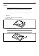
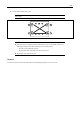
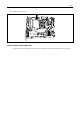
4. Connect the cables.
Check the connectors to which cables are to be connected for proper connections. Set the water-cooled heat
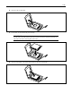
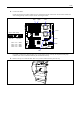
sink exchange jumper switch (CN6) as shown in the figure below.
Jumper switch setting
Water-cooling
heat sink
Standard
heat sink
If you fail to connect the cables properly or to set the jumper switch correctly, the liquid leak and pump
rotation of the water-cooled heat sink may be monitored incorrectly.
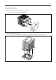
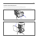
5. Remove the top cover from the CPU duct cover you have removed in the previous step.
FAN1 FAN5 CPU1
CPU2
FAN6
FAN4
CN6
CPU1 ↔ P1 ↔ FAN5
CPU1 ↔ P2 ↔ FAN1
CPU2 ↔ P1 ↔ FAN4
CPU2 ↔ P2 ↔ FAN6