
Use and Care Guide


to power assembly,
starting with front, use
4 (for the I-13), 5 (for the I-20), or 6
(for the I-26)
6mm x 16mm PH Phillips machine screws
(Hardware Kit part D. ).
Next, attach back of table to tail using 3 (for the I-13), 4 (for
the I-20), or 5 (for the I-26) #12 x 1” PH Phillips tapping screws
(Hardware Kit part E. ).
• Insert handle into cam shaft.
Note: back stroke stop must face upward!
• Tighten M16 x 40 bolt (pre-installed in
cam shaft) with 10mm hex wrench
(included).
4
For maximum security, the Safety Lock
will
AUTOMATICALLY RESET in the
“locked” position (A) unless disengaged.
Note: You must pull Safety Lock IN each time
you make a cut.
• Insert fence into one of the six hole sets on the
table: there are two 90° and four 45° locations
• The fence is friction fit (requires effort
to insert or remove)
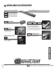
are available, such as Castors (#848-I) and a new Angle Guide Kit (#856AG) . See p. 10 for more information.
OPTIONAL ACCESSORIES
SET UP
3
4
5
6
ATTACH TABLE
TO ATTACH HANDLE,
PLACE THE FENCE
The Safety Lock can be DISENGAGED by
pulling the knob IN and hooking into slot
as shown below (B).
Note: It is important to
RE-ENGAGE LOCK AND
SECURE HANDLE
in down
position while storing,
carrying, or transporting
the Magnum Shear™.
SAFETY LOCK
NOTE:
Cam Shaft
Tip: begin threading
screws by hand, then
tighten with screwdriver
3A
3A
3B
3B
A
B
Back Stroke Stop