
Instructions / Assembly


INSTALLATION INSTRUCTIONS
Your Built-in Gas Grill comes to you fully assembled. We strongly recommend professional installation and hookup of the Gas BBQ grill. These
instructions will provide you with the measurements necessary for you or your builder to construct a masonry structure to house your outdoor gas
grill.
NOTE TO INSTALLER: Leave these instructions with the consumer for future reference. The grill must be installed in accordance with all local
building codes.
SPECIFICATIONS FOR BARBECUE STRUCTURE
1. Your choice of masonry can be used for cabinet construction for the built-in gas grill; however it must be non-combustible material. Keep in
mind when choosing a location for your grill that it should NOT be located under any overhead combustible construction. Upper and ground level
vents must be provided for combustion air on both sides of built-in cabinet. Vents on BBQ insert must remain unobstructed to allow for combustion
air and ventilation.
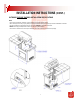
2. The BBQ grill requires a wall opening of the following dimensions: See PAGES 6 & 7 for different models.
3. Place gas grill assembly into wall opening as shown in illustration on pages 6 & 7. BBQ rests on side and back edges of the BBQ insert.
4. For propane gas LP TANK STORAGE AREA MUST BE ISOLATED FROM GRILL AND VENTED.
5. Do not use any combustible materials for this construction. Minimum horizontal clearance to adjacent combustible surface from side and back of
the grill must be 21 inches. A 6 inch clearance is required behind grill to allow front portion of hood to open and for ventilation purposes.
CONNECTING TO GAS SOURCE
Refer to the following instructions and illustrations for typical gas supply connections. We strongly suggest professional installation and hook-up of
the Gas BBQ.
IMPORTANT: Before connecting grill to gas source, make sure BBQ Grill control knobs are in “OFF” position.
5
PLEASE READ THESE INSTRUCTIONS BEFORE INSTALLING YOUR GAS GRILL
NATURAL GAS CONNECTIONS
IMPORTANT: Bull Outdoor Products does not recommend the use of any quick connect
fittings or lines to the unit. Use of these types of fittings or lines could cause low gas flow
and greatly reduce the performance of the unit.
- Pipe sealing compound or pipe thread tape of the type resistant to the
action of natural gas must be used on all male pipe thread.
- Apply compound or tape to at least the first three threads when making the connection.
- Remove plastic cap from regulator installed on grill.
- Attach stainless steel flex line 3/8” flare-female end to the regulator.
- Attached the other end of flex line to shut-off valve through a nipple.
- Attach a shut-off valve to gas supply pipe.
PERFORM GAS LEAK CHECK – REFER TO PAGE 2
PROPANE GAS CONNECTIONS
- In the United States, the LP gas pressure regulator and hose assembly supplied with this
unit must be used without alteration. If this assembly needs to be replaced, use only the
type 1 specified in the parts list supplied with this unit. Use a LP tank with a type 1 cylinder
valve.
- Make sure the tank is firmly secured in an upright position.
- Turn the black coupling nut of the hose and regulator assembly in a clockwise direction.
- Make sure it is completely threaded onto the cylinder valve before turning gas supply on.
PERFORM GAS LEAK CHECK – REFER TO PAGE 2