INSTALLATION Manual John Deere 8030 and 8020 Series Module Applications John Deere 8130 to 8530 John Deere 8230T to 8430T John Deere 8120 to 8520 John Deere 8120T to 8520T Rapid Power Part # 40605 40605 40605 40605
TABLE OF CONTENTS TROUBLESHOOTING: If you have questions during the installation of this product, please visit www.bullydog.com/Product_Updates.php. The latest version of these instructions can be found at the same location. Technical support is available by calling 866-bullydog (866-285-5936). TABLE OF CONTENTS INTRODUCTION................................................................................................pg. 2 Parts DESCRIPTIONS................................................................
INTRODUCTION Product Description: The product is made up of two different parts, the module box, and cable. Contents: 1. Rapid Power Module with Wiring Harness 2. Zip Ties The module box: The module box contains the electronics that will allow your tractor to produce more horsepower. It is very important that this module is mounted away from all moving or hot parts. The box should be placed in an area protected from dirt and moisture.
RPM DESCRIPTION Air Filter MAP Sensor Fuel Rail Pressure Sensor 8030 Series Product placement overview: 3
RPM INSTALLATION Installation instructions: 1. Open Hood of Tractor, install module when engine is not running and cool. 2.: Place module below the air filter in a safe location and run cable along the wiring harness toward the top of the engine. 3. Remove plug from the MAP sensor located at the top of the engine. Note: Make sure the gray cap is securely fastened to male plug and is not in the MAP Sensor.
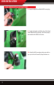
RPM INSTALLATION 4. Plug tractor male plug into module female plug Module Female Plug 5. Plug the module male plug into the tractor MAP sensor. Module Male Plug 6. Continue routing module cable along the wiring harness above the engine. Run the cable down between the engine block and starting fluid can to the location shown. Module cable run 7.:Disconnect the plug from the factory fuel rail pressure sensor.
RPM INSTALLATION 8. Insert module female plug into fuel rail pressure sensor. Fuel Rail Sensor Plug Module Female Plug 9. Connect the module male plug to the tractor female plug. Module Male Plug Fuel Rail Sensor Female Plug 10. Use zip ties to secure the Rapid Power cable to the tractor wiring harness. Be sure the cable will be safe from moving parts (such as the starter/flywheel) or hot exhaust system parts. Zip tie the module box to the cable harness as shown.
RPM INSTALLATION 8020 SERIES INSTALL INSTRUCTIONS The Rapid Power module will increased power and capability for your 8020 series tractor. Without changing the wiring harness the Rapid Power Module can be modified to work with the 8020 series tractor. The Module will provide you the power and reliability that you have come to expect from Bully Dog Technologies. 1.: Open Hood of Tractor, install module when engine is not running and is cool. 2.
RPM INSTALLATION 5.: Route the Rapid Power fuel pressure sensor cable to the fuel rail pressure sensor. 6.: Insert the Rapid Power module female fuel pressure sensor plug to the male fuel pressure sensor. 7.: Insert the Rapid Power module male fuel pressure sensor plug to the female fuel pressure sensor.
RPM INSTALLATION 8020 SERIES INSTALL INSTRUCTIONS 8.: Locate the Rapid Power Module MAP sensor plugs. 9.: Couple the Female and Male ends of the Rapid Power Module MAP sensor plugs. Use of these plugs is not needed on the 8020 Series tractors. 10.: Attach the MAP sensor plugs to the main cable using a zip tie that will secure the plugs for future use.
RPM INSTALLATION 11.: Zip Tie module and loop and zip tie any remaining cable. Ensure that the cable and module will be safe from moving parts (such as the starter/flywheel) or hot exhaust system parts. Warning: Do not remove module while tractor is running. Shut down machine and then remove module.
OPERATING INSTRUCTIONS Operating Instructions: Internal power level switch: The Rapid Power module has three power settings, Stock, Low Power Level or High Power Level. To select different power levels remove the cover of the module box, locate the red internal power switch, and set the switch to the desired power level per illustrations below. High Power Level These two positions provide the same power.
OPERATING INSTRUCTIONS INTERNET UPGRADES/Update agent IMPORTANT: The information on this page is applicable to all vehicles and tractors. Internet Update The Rapid Power Module is internet updatable. To update remove cover from the module and insert a USB cable into the USB port. Ensure that you have downloaded the Update Agent. The Update Agent will automatically recognize the module and prompt you to update the module if an update is available. Simply visit Bully Dog’s web site www.bullydog.
INTERNET UPDATE USB Driver Installation (Windows XP only!) IMPORTANT: Install the Update Agent prior to plugging in your module . Your computer will not recognize the Module until the Driver is installed. 1) Remove cover from Rapid Power Module 2) Plug Module into PC using a USB cable (Male A end for PC, Male B end for Module: Same type of cable as used for most printers) 3) Windows will recognize the Module and attempt to install software.
INTERNET UPDATE 7) Windows will warn that this driver is not signed, but select continue anyway! 8) Allow the driver installation to complete and click FINISH 9) The Update Agent should now recognize the device and allow the update to take place.
Doc.# 40605-99 V2.0 Check out more of our Adrenaline Pumping products! Downloaders Intake Systems Triple Dog GT Exhaust Systems ® Free Technical Support at: 866-bullydog (866-285-5936) See More at: bullydog.