INSTALLATION Manual CAT 3126 ,C7and C9engines Applications 3126 ‘98-’03 C7 ‘98-’05 C9 ‘98-’05 Rapid Power Part # 40630 40630 40630
TABLE OF CONTENTS INTRODUCTION You have just purchased the most technologically advanced tractor module available for the CAT engines series 3126, C7 and C9. The Rapid Power module is the safest and longest lasting module on the market. The Rapid Power module also comes with free technical support and internet update ability, just call: 1-866-285-5936.
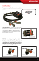
INTRODUCTION Parts Description: The product is made up of two different parts, the module box, and cable. Contents: 1. Rapid Power Module with Wiring Harness 2. Zip Ties The module box: The module box contains the electronics that will help the engine to produce more horsepower. It is very important that this module is mounted away from all moving or hot parts. The box should be placed in an area protected from dirt and moisture.
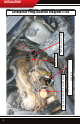
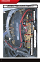
3 Injection Control Pressure Sensor Juncture Injection Control Pressure Sensor MAP Sensor MAP Sensor Juncture INSTALLATION Caterpillar Plug Location Diagram 3126
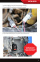
INSTALLATION 1. Open the engine compartment or remove the engine cover, make sure that the engine is fully accessible so that plugs can be reached and the module can be mounted to a safe place within the engine bay. 2. Locate the MAP Sensor plug near the back of the engine on the right side of the engine and near the rear of the engine. Reference this map sensor when following step 3. L R F B 3.
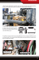
INSTALLATION 4. Plug the male OEM MAP sensor plug into the female Module MAP sensor plug. MAP w/ Rapid Power connected 5. Plug the female OEM MAP sensor plug in the male Module MAP sensor plug. 6. Locate the ICP Sensor: like with the MAP sensor plug, locate the ICP sensor and then follow the connected wire harness to the plug set and disconnect that plug set in preparation to tie in the Bully Dog harness. The Injection Control Pressure sensor is located on the right side of the engine near the front.
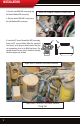
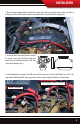
INSTALLATION 7. Plug the male OEM ICP sensor plug into the female Module ICP sensor plug. 8. Plug the female OEM ICP sensor plug in the male Module ICP sensor plug. 9. Mount and secure the Rapid Power module in a location that is away from exteme heat and moving parts. Use the zip ties included with the package to secure all of the wiring and the module itself. Warning: Do not remove module while engine is running. Shut down machine and then remove module.
7 MAP Sensor Juncture Injection Control Pressure Sensor Juncture Injection Control Pressure Sensor MAP/Boost Sensor INSTALLATION Caterpillar Plug Location Diagram C7
INSTALLATION 1. Open the engine compartment or remove the engine cover, make sure that the engine is fully accessible so that plugs can be reached and the module can be mounted to a safe place within the engine bay. 2. Locate the MAP Sensor plug near the back of the engine on the right side of the engine and near the rear of the engine. Reference this map sensor when following step 3. L R F B 3. Locate Map/Boost sensor plugs: The MAP sensor will have a tag on it with the label “Boost,” on it.
INSTALLATION 4. Plug the male OEM MAP sensor plug into the female Module MAP sensor plug. MAP w/ Rapid Power connected 5. Plug the female OEM MAP sensor plug in the male Module MAP sensor plug. 6. Locate the ICP Sensor: once located then follow the connected wire harness to the triangle shaped plug set and disconnect that plug set in preparation to tie in the Bully Dog harness. The Injection Control Pressure sensor is located on the right side of the engine near the front.
INSTALLATION 7. Plug the male OEM ICP sensor plug into the female Module ICP sensor plug. 8. Plug the female OEM ICP sensor plug in the male Module ICP sensor plug. 9. Mount and secure the Rapid Power module in a location that is away from exteme heat and moving parts. Use the zip ties included with the package to secure all of the wiring and the module itself. Warning: Do not remove module while engine is running. Shut down machine and then remove module.
OPERATING INSTRUCTIONS Operating INSTRUCTIONS Internal power level switch: The Rapid Power module has three power settings, Stock, Low Power Level or High Power Level. To select different power levels remove the cover of the module box, locate the red internal power switch, and set the switch to the desired power level per illustrations below. Be sure to securely fasten the module cover after changing the power level. Make sure the cable exits the box properly in the hole provided.
OPERATING INSTRUCTIONS INTERNET UPGRADES/Update agent IMPORTANT: The information on this page is applicable to all vehicles and tractors. Internet Update The Rapid Power Module is internet updatable. To update remove cover from the module and insert a USB cable into the USB port. Ensure that you have downloaded the Update Agent. The Update Agent will automatically recognize the module and prompt you to update the module if an update is available. Simply visit Bully Dog’s web site www.bullydog.
INTERNET UPDATE USB Driver Installation (Windows XP only!) IMPORTANT: Install the Update Agent prior to plugging in your module . Your computer will not recognize the Module until the Driver is installed. 1) Remove cover from Rapid Power Module 2) Plug Module into PC using a USB cable (Male A end for PC, Male B end for Module: Same type of cable as used for most printers) 3) Windows will recognize the Module and attempt to install software.
INTERNET UPDATE 7) Windows will warn that this driver is not signed, but select continue anyway! 8) Allow the driver installation to complete and click FINISH 9) The Update Agent should now recognize the device and allow the update to take place.
Doc.# 40630-99 V2.0 Check out more of our Adrenaline Pumping products! Downloaders Intake Systems Triple Dog GT Exhaust Systems ® Free Technical Support at: 866-bullydog (866-285-5936) See More at: bullydog.