PRECISION WATER SERIES SERVICE MANUAL BUNN-O-MATIC CORPORATION POST OFFICE BOX 3227 SPRINGFIELD, ILLINOIS 62708-3227 PHONE: (217) 529-6601 FAX: (217) 529-6644 To ensure you have the latest revision of the manual or to obtain the illustrated parts catalog, please visit the Bunn-O-Matic website, at www.bunn.com. This is absolutely FREE, and the quickest way to obtain the latest catalog and manual updates.
BUNN-O-MATIC COMMERCIAL PRODUCT WARRANTY Bunn-O-Matic Corp. (“BUNN”) warrants equipment manufactured by it as follows: 1) Airpots, thermal carafes, decanters, GPR servers, iced tea/coffee dispensers, MCR/MCP/MCA single cup brewers, thermal servers and ThermoFresh® servers (mechanical and digital) 1 year parts and 1 year labor. 2) All other equipment - 2 years parts and 1 year labor plus added warranties as specified below: a) Electronic circuit and/or control boards - parts and labor for 3 years.
WARNING - Inspection, testing, and repair of electrical equipment should be performed only by qualified service personnel. Disconnect the dispenser fromthe power source when servicing, except when electrical tests are required and the test procedure specifically states to connect the dispenser to the power source. CONTENTS TroubleShooting............................................................................................. 4 Component Access...........................................................
TROUBLESHOOTING A troubleshooting guide is provided to suggest probable causes and remedies for the most likely problems encountered. If the problem remains after exhausting the troubleshooting steps, contact the Bunn-O-Matic Technical Service Department. • • • • • • • Inspection, testing, and repair of electrical equipment should be performed only by qualified service personnel. All electronic components have 120 – 240 volt ac and low voltage dc potential on their terminals.
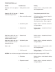
TROUBLESHOOTING (cont.) Problem Probable Cause Remedy Equipment will not operate (cont.) 2. Safety overflow switch Refer to Service – safety overflow switch for testing procedures. Automatic refill will not oper- 1. No water ate after drawing hot water. 2. Water strainer/flow control Check plumbing and shut-off valves. (A) Direction of flow arrow must be pointing towards dispenser. (B) Remove the strainer/flow control and check for obstructions. Clear or replace. 3.
TROUBLESHOOTING (cont.) Problem Probable Cause Remedy Water boils continuously. 1. Temperature control Refer to Service – electronic controls for testing procedures. 2. Lime build-up Inspect the tank assembliy for excess lime deposits. Delime as required. CAUTION – Tanks and tank components should be delimed reglarly depending on local water conditions. Excessive mineral build-up on stainless steel surfaces can initiate corrosive reactions resulting in serious leaks. Dispenser is making unusual 1.
SERVICE WARNING – Disconnect the dispenser from the power source before the removal of any panel or the replacement of any component. WARNING - Inspection, testing, and repair of electrical equipment should be performed only by qualified service personnel. Disconnect the dispenser fromthe power source when servicing, except when electrical tests are required and the test procedure specifically states to connect the dispenser to the power source.
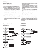
SERVICE Liquid Level Control Flow Charts Electronic Controls H3/5/10 LEVEL CONTROL H5E, H5XLIQUID LIQUID LEVEL CONTROL PROBLEM: Does Not Refill Overflow Cup Full ? Yes Remove Power Drain cup No Retry Disconnect Level Probe Voltage present at Solenoid Valve ? No H5 Th co is mp eq ly uip Ad thewith ment mi the is an nis Bu of d the tra ildingBasicto be tor the ins Of Fo Foods Int fic Plum tal od er ial bin led an Servi natios an g d Dr ce na d Co to Co de ug Sa l, Inc de of Ad nit mi ation.
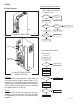
SERVICE (cont.) Electronic Controls (cont.) 4. Remove the pink wire from terminal 5 of the electronic control assembly. 5. Check the voltage across terminals 1 & 4 of the electronic control board with a voltmeter. Connect the dispenser to the power source. The indication must be: a.) 100 to 120 volts ac for 100 to 120 voltmodels or b.) 200 to 240 volts ac for 200 to 240 volt models or c.) 230 volts ac for 230 volt models after a delay of approximately 5 seconds. 6.
Electronic Controls (cont.) If voltage was not present as described, check the pink probe wire and the green ground wire for continuity and/or replace the probe. 7. Reconnect the pink wire to terminal 5 of the electronic control assembly. 8. Loosen the compression fitting, remove the probe from the tank lid, and inspect it for mineral deposits. Replace it if necessary. Keep the exposed ends of the probe away from any metal surface of the dispenser. 9.
SERVICE (cont.) Electronic Controls (cont.) If voltage was present as described, the temperature control of the system is operating properly. If voltage was not present as described, contact Bunn-O-Matic to order an electronic control board and temperature sensor for evaluation and proceed to #9. 6. Replace the electronic control board. T5 PNK to Liquid Level Probe 7. Check the voltage across the tank heater terminals with a voltmeter. Connect the dispenser to the power source. The indication must be: a.
SERVICE (cont.) If voltage was present as described, reconnect the black wire and proceed to #5. If voltage was not present as described, refer to the Wiring Diagrams and check the dispenser wiring harness. Limit Thermostat Location: The limit thermostat is located on the tank lid. To test the limit thermostat, access will also be needed to the terminal block located at the rear of the dispenser. 5. Check for continuity across the terminals of the limit thermostat.
SERVICE (cont.) Removal and Replacement: 1. Disconnect the black wires from the safety overflow switch. 2. Remove the nut beneath the copper overflow cup. 3. Remove the entire switch assembly from the cup. 4. Place the new switch assembly into the cup, wires first. Make sure that a gasket is in place around the threaded switch stem.
SERVICE (cont.) sound after approximately 5 seconds, as the coil magnet attracts the plunger. 8. Disconnect the dispenser from the power source. 9. Reconnect the pink wire to terminal 5 of the electronic control board. Solenoid Valve (Late Models) Location: The solenoid valve is located inside the rear of the dispenser on the right side near the bottom. To test the solenoid valve, access will also be needed to the electronic control board.
SERVICE (cont.) Solenoid Valve (Early Models) If continuity is present as described, reconnect the wires and proceed to #7. If continuity is not present as described, replace the solenoid valve coil. Location: The solenoid valve is located behind the large access panel on the left side of the dispenser. To test the solenoid valve, access will also be needed to the electronic control board. 7. Check the solenoid valve for coil action. Connect the dispenser to the power source.
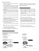
SERVICE (cont.) Tank Heater Location: The tank heater is located in the tank lid. 4. Remove the tank heater from the tank lid and inspect it for cracks in the sheath. If the sheath shows no sign of damage, proceed to #5. If the sheath is damaged, replace the tank heater. 5. Check for continuity across the tank heater terminals. H5 FIG. 16a TANK HEATER If continuity is present as described, reinstall the tank heater. The tank heater is operating properly.
SERVICE (cont.) Removal and Replacement: 1. Disconnect the dispenser from the power source. 2. Disconnect the thermistor from J5 on control board. 3. Loosen the set screw and the two screws securing the two half blocks together. Remove thermistor assembly from overflow tube. 4. Install new thermistor on tube and slide down until it contacts the flared end. NOTE: It’s critical that the thermistor be centered directly under the tube opening. 5.
SERVICE (cont.) Dispense Valve (PC & H3 Element Only) Location: The Dispense Valve is located behind control panel. If voltage is not present as described, refer to Wiring Diagrams and check the dispenser wiring harness. Also check the control board for proper operation. Removal and Replacement: 1. Disconnect the dispenser from the power source and allow to cool. 2. Drain enough water from the tank so the water level is below the outlet. 3. Remove the nut and flare nut from the valve. 4.
SERVICE (cont.) Dispense Valve (PC & H3 Element Only) Location: The Dispense Valve is located behind control panel. Removal and Replacement: 1. Disconnect the dispenser from the power source and allow to cool. 2. Drain enough water from the tank so the water level is below the outlet. 3. Remove the top cover (3 screws) and front shroud (4 screws). 4. Loosen snap clamp and remove silicon dispense nozzle. 5. Remove the two screws securing the valve. 6. Disconnect wires from the valve. 7.
SERVICE (cont.) Dispense Switch (H3E Element Only) Location: The dispense switch is located in the control panel. Shroud (+) Y AD RE MP TE DE R GY ER EN VE SA R MO F OF ATE HE ON Dispense switch FIG. 20a DISPENSE SWITCH Removal and Replacement: 1. Disconnect the dispenser from the power source. 2. Remove the top cover (3 screws) and front shroud assembly (4 screws). 3. Remove the top 2 screws and loosen 2 lower screws securing control panel to shroud. 4.
SERVICE (cont.) Thermostat (H5M, HW2 & OHW Only) Location: The mechanical thermostat is located inside the upper rear panel. To test the thermostat, access will also be needed to the terminal block located inside the bottom access panel. If voltage is not present as described, replace the thermostat. Removal and Replacement: 1. Remove both wires from the thermostat terminals. 2. Remove the top lid from the dispenser to gain access to the thermostat bulb. 3.
SERVICE (cont.) If voltage is not present as described refer to the Wiring Diagrams and check the wiring harness. Contactor (H5M Only) 5. Check for continuity between the left and right terminals on the contactor coil. If continuity is present as described, reconnect the wires and proceed to #6 If continuity is not present as described, replace the contactor. 6. Check the voltage across the upper left terminal and the upper right terminal on the contactor with a voltmeter.
SERVICE (cont.) from any metal surface of the dispenser. 7. Check the voltage across terminals 1 & 3 with a voltmeter. Connect the dispenser to the power source. Turn the thermostat knob to the “ON” position (fully clockwise). The indication must be: a.) 100 to 120 volts ac for 100 to 120 volt models, b.) 200 to 240 volts ac for 200 to 240 volt models, c.) 230 volts ac for 230 volt models, after a delay of approximately 5 seconds. 8. Touch the free end of jumper wire to the dispenser housing.
SERVICE (cont.) 2. Remove two #8-32 screws holding level control board and mounting bracket to the component bracket. 3. Install the new level control board and mounting bracket to the component bracket. 4. Refer to FIG. 12 when reconnecting the wires. Liquid Level Board (cont.) (H5M & HW2 Only) 15. Move the probe’s flat end to the dispenser housing. The indication must be 0. 16. Move the probe’s flat end away from the dispenser housing. The indication should again be: a.
SCHEMATIC WIRING DIAGRAM H5E-DV PC L1 N L2 GRN RED-14 BLK-14 Earth Ground MASTER ON/OFF SWITCH Chassis Ground RED-14 BLK-18 SELECTOR SWITCH N.C. OVERFLOW PROTECTION SWITCH BRN-14 4000 W BLK-18 WHI/BLU-18 4 3 WHI-18 2 J7 1 VIO-18 CONTROL 120VAC SOL 120VAC SOL REFILL WHT-18 WHT-18 DISPENSE 5 4 3 2 1 COM MAIN TANK HEATER WHT-14 1800 W N.O. RELAY PINK-22 J6-1 GRN-18 BOARD J2 6 1 FACTORY TANK HEATER WHI/VIO-14 BLU-14 LIMIT THERMOSTAT BLK-14 BLK-14 + 0-3.
L1 GRN Earth Ground Chassis Ground SCHEMATIC WIRING DIAGRAM H5E-PC L2 RED-14 BLK-14 EMI FILTER BLK-18 RED-14 LIMIT THERMOSTAT BLK-14 BLK-14 TANK HEATER BLU-14 4000 W BLU-14 N.C. OVERFLOW PROTECTION SWITCH BLK-18 3 RED-18 2 J7 1 VIO-18 COM MAIN CONTROL RED-18 DISPENSE 230VAC SOL RED-18 5 4 3 2 1 N.O. RELAY PINK-22 J6-1 GRN-18 BOARD J2 6 1 FACTORY REFILL 230VAC SOL WHI/BLU-18 4 LIMIT THERMOSTAT + 0-3.3VDC J4-1 + 0-3.
SCHEMATIC WIRING DIAGRAM H5-PC 200V L1 GRN/YEL L2 or N TERMINAL BLOCK BLK RED MASTER ON/OFF SWITCH Earth Ground Chassis Ground BLU/BLK BRN/WHI RFI SUPPRESSION CAPACITOR EMI FILTER BRN/BLK TANK HEATER BRN/WHI N.C. OVERFLOW PROTECTION SWITCH BLU BLK 2 1 4 3 4 2 J2 MAIN CONTROL BOARD DISPENSE REFILL WHI/VIO SOL VIO SOL WHI/RED 3 1 BRN NO 5 4 3 2 1 COM RELAY PINK-22 J6-1 GRN-18 0-3.3VDC + 0-3.
SCHEMATIC WIRING DIAGRAM H10X L1 GRN L2 or N Earth Ground MAIN ON/OFF SWITCH (Late Models only) Chassis Ground BLK-18 WHI/VIO-14 BLK-14 BLK-14 TRIAC LIMIT THERMOSTAT BLK-14 BLK-14 WHI/VIO-14 BLU-14 TANK HEATER TRIAC LIMIT THERMOSTAT BLK-14 BLK-14 RED or WHI-18 BLU-14 TANK HEATER OVERFLOW PROTECTION SWITCH RED RED BLK-18 4 3 2 1 J7 BLU-20 TAN-20 BLU-20 BLU-18 BRN/BLK-18 TAN-20 N.O.
SCHEMATIC WIRING DIAGRAM H5E/H5X L1 GRN L2 or N Earth Ground MAIN ON/OFF SWITCH (Late Models only) Chassis Ground BLK-18 LIMIT THERMOSTAT BLK-14 BLK-14 RED or WHI-18 BLK-14 BLU-14 TANK HEATER OVERFLOW PROTECTION SWITCH RED RED BLK-18 BLU-20 3 2 1 J7 WHI/VIO-14 BLU-18 4 N.O. COM MAIN CONTROL PINK-22 5 4 3 2 1 RELAY RED-18 or WHI-18 RED-18 or WHI-18 GRN-18 WHI/BLU-18 J6-1 BOARD J2 6 1 FACTORY + 0-3.3VDC J4-1 + 0-3.
SCHEMATIC WIRING DIAGRAM H5XA, H5EA (CE) GRN/YEL L1 L2 Earth Ground Chassis Ground BLK-14 LIMIT THERMOSTAT BLK-14 BLK-14 BLU-14 LIMIT THERMOSTAT TANK HEATER RFI SUPPRESSION CAPACITOR BLK-18 RED-18 EMI FILTER BLK-18 OVERFLOW PROTECTION SWITCH RED RED 4 3 2 1 BLK-18 BLU-14 J7 WHI/VIO-14 MAIN CONTROL BOARD RED-18 PINK-22 5 4 3 2 1 N.O. COM RED-18 GRN-18 WHI/BLU-18 SOL RED-18 RELAY J6-1 J2 6 1 FACTORY 5 10 USE ONLY 0-3.3VDC 0-3.
GRN or GRN/YEL SCHEMATIC WIRING DIAGRAM H5 ELEMENT L1 L2 or N Earth Ground TERMINAL BLOCK BLK Chassis Ground RED MASTER ON/OFF SWITCH BLK WHI/BLU BRN/BLK RED TANK HEATER BRN/WHI N.C. OVERFLOW PROTECTION SWITCH LIMIT THERMOSTAT BLU BLK 2 1 4 3 REFILL TAN J2 4 2 SOL WHI/RED 3 1 BRN MAIN CONTROL BLK BOARD J1 1 5 N.O.
SCHEMATIC WIRING DIAGRAM H5 ELEMENT 220-240V (CE) L1 N TERMINAL BLOCK GRN/YEL BRN BLU MASTER ON/OFF SWITCH Earth Ground Chassis Ground BLU/BLK BRN/WHI RFI SUPPRESSION CAPACITOR EMI FILTER BRN/BLK WHI/BLU TANK HEATER BRN/WHI N.C.
SCHEMATIC WIRING DIAGRAM H3EA ELEMENT 230V (CE) L1 N TERMINAL BLOCK GRN/YEL BRN BLU MASTER ON/OFF SWITCH Earth Ground Chassis Ground BLU BLU/BLK BRN/WHI EMI FILTER BRN/BLK WHI/BLU TANK HEATER BLU LIMIT THERMOSTAT BRN BLK REFILL BRN/WHI TAN SOL DISPENSE WHI/YEL SOL J2 4 3 2 1 WHI/RED YEL TRIAC TAN MAIN CONTROL BLK BLK BOARD 1 J1 5 RELAY BLU BRN/BLK RED TAN DISPLAY 1 J5 PINK GRN/YEL J4-1 + BLK WHI J2-1 +- BLK J3-1 5 BOARD DISPENSE SWITCH J1-1 TEMP PROBE WHI REF
SCHEMATIC WIRING DIAGRAM H3E ELEMENT 120V L1 N TERMINAL BLOCK GRN Earth Ground Chassis Ground WHI WHI/BLU TANK HEATER BLK LIMIT THERMOSTAT WHI/YEL WHI/BLU BLK BLK BLU TAN REFILL DISPENSE SOL SOL J2 4 3 2 1 WHI/RED YEL BLU TRIAC WHI TAN MAIN CONTROL BOARD 1 J1 5 RELAY BLU CURRENT LIMITING RESISTOR BRN/BLK RED TAN DISPLAY PINK GRN/YEL J4-1 + BLK WHI J2-1 +- BLK J3-1 J5 1 5 BOARD DISPENSE SWITCH TEMP PROBE WHI J1-1 REFILL PROBE J1-5 TANK t° 44657.
SCHEMATIC WIRING DIAGRAM H5M L1 WHI N BLK GRN MAIN ON/OFF SWITCH (Late Models only) OPTIONAL READY INDICATOR BLK BLK SW& THERMOSTAT BLK LIMIT THERMOSTAT BLU/BLK BLK BLK WHI TANK HEATER LIQUID LEVEL BOARD 1 2 3 4 OVERFLOW PROTECTION SWITCH RED RED BLU BLK WHI SOL WHI P N K (PROBE) 120 VOLTS A C 2 WIRE + GND SINGLE PHASE 10243.
SCHEMATIC WIRING DIAGRAM HW2 L1 SW. & THERMOSTAT BLK N GREEN LIMIT THERMOSTAT BLK BLK 1700W WHI TANK HEATER 40W WHI WHI KEEP WARM HEATER WHI 40W WHI KEEP WARM HEATER BLK RED SAFETY SW LIQUID LEVEL BOARD 1 2 3 4 RED BLU/BLK BLK SOL WHI WHI P N K (PROBE) 120 VOLTS A C 2 WIRE SINGLE PHASE 10261.0000E 5/98 © 1987 BUNN-O-MATIC CORPORATION SCHEMATIC WIRING DIAGRAM HW2A GRN/YEL L1 L2 SW.
SCHEMATIC WIRING DIAGRAM OHW GRN L1 120 VOLTS A C 2 WIRE SINGLE PHASE 60 HZ BLK THERMOSTAT BLK N 1000W BLK WHI WHI TANK HEATER 40W WHI WHI KEEP WARM HEATER 10269.0000B 6/98 © 1988 BUNN-O-MATIC CORPORATION SCHEMATIC WIRING DIAGRAM OHWA GRN/YEL L1 230 VOLTS A C 2 WIRE SINGLE PHASE 50 HZ BLK THERMOSTAT BLK BLK L2 1000W RED RED TANK HEATER 34W WHI RED KEEP WARM HEATER 10269.