
Service and Repair Manual


23
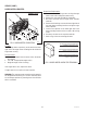
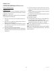
FIG. 2 AUGER MOTOR TERMINALS
Location
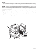
The auger motors are located at the upper rear of the
dispenser chassis inside the auger motor covers.
Test Procedures
1. Remove the hopper from the same side as the motor
to be tested.
2. Turn “ON” the appropriate auger switch.
3. Nudge the auger to start it turning.
If the auger doesn’t turn, replace the motor.
If auger starts to turn, replace the start capacitor.
WARNING: The compressor start capacitor must be properly
discharged before removing. This is most commonly done
on low voltage capacitors by shorting across the terminals
with a screwdriver.
SERVICE(CONT.)
AUGER MOTORS
FIG. 1 AUGER MOTORS
P1341
J1-1 Boost C
oil
J1-2 Run Coil
J1-3 Common
ULTRA-2 LEFT AUGER MOTOR
J1-1 BRN/WHI to Left Auger Motor Capacitor
J1-2 BRN/BLK to J5-3 of Control Board
J1-3 WHI to Main Harness
ULTRA-2 RIGHT AUGER MOTOR
J1-1 WHI/RED to Right Auger Motor Capacitor
J1-2 RED/BLK to J5-1 of Control Board
J1-3 WHI to Main Harness
ULTRA-1 AUGER MOTOR
J1-1 BRN/WHI to Auger Motor Capacitor
J1-2 BRN/BLK to J10-9 of Control Board
J1-3 WHI to Main Harness
MOTOR COIL RESISTANCE
J1-3 to:
WHITE
J1-2 = 58 ohms
RED
J1-1 = 58 ohms
BLACK
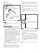
Removal and Replacement
1. Remove the two #8 locking screws securing the auger
motor cover to the cooling drum mount assembly.
2. Remove the cover and set aside for reassembly.
3. Remove the #8 locking screw on the lower right side of
the auger motor mounting bracket securing the auger
motor run capacitor. Set capacitor aside with wires at-
tached.
4. Disconnect the auger motor terminal from the terminal
on the main wiring harness.
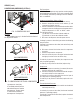
5. Remove the three remaining #8 locking screws secur-
ing the auger motor mounting bracket to cooling drum
mounting bracket.
6. Remove motor with mounting bracket, drip tray, split
pin and torsion spring bearing as an assembly.
NOTE: When removing or installing the motor be sure the
split pin in the motor shaft is turned to a position that will
clear the torque sensor circuit board.
7. Install new motor with mounting bracket, drip tray, split
pin and torsion spring bearing using three #8 locking
screws onto the cooling drum bracket.
8. Install the auger motor capacitor on the lower right side
of the auger mounting bracket, using the remaining #8
locking screw.
9. Connect the auger motor terminal to the terminal on the
main wiring harness.
10. Refer to Fig. 2 when reconnecting the wires.
ULTRA-2 shown
41084 102709