
Service and Repair Manual


26
SERVICE (cont.)
AUGER SHAFT ASSEMBLY(cont.)
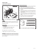
FIG. 7 COOLING DRUM SEAL
P1760
Open face of seal away
from tool
Cooling Drum Seal
Seal Insertion Tool
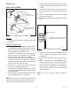
FIG. 8 MOTOR/SHAFT ASSEMBLY
P1761
Lube about 1 1/2” of shaft and
in the groove with #29563.0000
“Krytox” Lubricant
Auger Shaft Assy
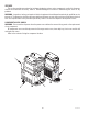
14. Assemble motor/shaft assembly as shown in Fig.
8, then install assembly into cooling drum. Make
sure the pins do not hit the sensor board and cool-
ing drum seal is not dislodged as the shaft passes
through.
15. Secure motor and capacitor to the cooling drum
mounting bracket. Install rear motor cover.
16. Refer to Hopper Installation for hopper assembly
and installation procedures. Be sure to use new
hopper/drum seal and faucet seals
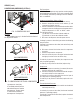
17. Remove and clean condenser air filter, Fig. 10.
18. Refer to the Programming Manual, “Menu Function
Index”. Scroll to menu “PM Complete?” and answer
“YES” to reset the reminder message “PM Due”.
P3682
FIG 10
FIG 9
ULTRA-2 shown
41084 102709