
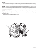
Service and Repair Manual


27
9
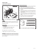
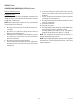
FIG. 11 CIRCUIT BREAKER (ULTRA-2)
SERVICE (cont.)
CIRCUIT BREAKER
Location:
The circuit breaker is located inside the dispenser
on the front right frame post on ULTRA-2 models; and
under the Auger Motor cover on ULTRA-1 models.
Test Procedures:
1. Disconnect the dispenser from the power source.
2. Remove the wires from the circuit breaker.
3. Check for continuity between the terminals. Conti-
nuity must be present between the terminals.
If continuity is present as described the circuit breaker
is functioning properly.
If continuity is not present as described, press the reset
button and repeat step #3, if continuity is not present
as described, replace the circuit breaker.
Removal and Replacement:
1. Remove the right side panel on ULTRA-2 models;
or remove the Auger Motor cover on ULTRA-1
models.
2. Remove the wires from the circuit breaker.
3. Compress the clips on the back side of the com-
ponent bracket and gently push the circuit breaker
through the opening in the bracket.
4. Push the new circuit breaker into the opening in
the bracket until the clips snap into position.
5. Reconnect the wires to the circuit breaker.
6. Refer to Fig. 13 when reconnecting the wires.
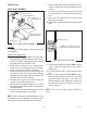
FIG. 13 CIRCUIT BREAKER TERMINALS
WHI/BLU from Transformer
WHI/YEL to Lamp Relay (ULTRA-2)
RED to Lamp Relay (ULTRA-1)
9
R
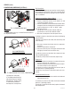
FIG. 12 CIRCUIT BREAKER (ULTRA-1)
41084 102709