
Service and Repair Manual
3
USER NOTICES
All notices on this equipment are written for your protection. All notices are to be kept in good condition.
Replace any unreadable or damaged labels.
CONTENTS
Warranty ...................................................................................................................................2
User Notices .............................................................................................................................3
Site Preparation .......................................................................................................................3
Introduction ..............................................................................................................................4
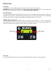
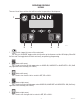
Operating Controls .................................................................................................................... 6
Preventive Maintenance
Recommended Cleaning ....................................................................................................8
Auto-fill Cleaning Instructions ...........................................................................................10
Preventive Maintenance Schedule .....................................................................................11
Troubleshooting ................................................................................................................14
Service
Access Panels ...................................................................................................................22
Auger Motors .................................................................................................................... 23
Auger Motor Capacitors ....................................................................................................24
Auger Shaft Assembly .......................................................................................................25
Circuit Breaker ..................................................................................................................27
Compressor ......................................................................................................28,31,38,41
Relay (or Contactor on Early Models) ...............................................................................43
Control Board ....................................................................................................................44
Cooling Drum Alignment ...................................................................................................45
Fan ...............................................................................................................................46,47
Hot Gas Sensor ................................................................................................................. 48
Lamp Cord Assembly ........................................................................................................49
Lamp Cord Connector ....................................................................................................... 50
Lamp Holder/Socket Assembly .........................................................................................51
LED Lamps .......................................................................................................................52
Lamp Relay .......................................................................................................................53
Membrane Switch ........................................................................................................54,55
Solenoids ..........................................................................................................................56
Temperature Sensor Assembly .........................................................................................57
Torque Sensor Circuit Board .............................................................................................58
Transformer .....................................................................................................................59
Auto Fill Systems .........................................................................................................60,62
Coolant Schematics ...........................................................................................................64,65
Electrical Schematics ..............................................................................................................66
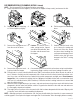
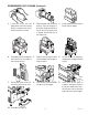
SITE PREPARATION
The dispenser must have at least four inches of space behind it. This space is needed for airflow, air filter
removal, and cleaning. Minimal clearance is required between the dispenser sides and the wall or another appli-
ance. The dispenser performs better if not placed near any heating appliance. Leave some space so the dispenser
can be moved for cleaning.
41084 081216