
Service and Repair Manual


32
SERVICE (cont.)
COMPRESSOR (EMBRACO) (ULTRA-2) (cont.)
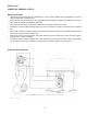
Compressor Thermal Overload Protector: Refer to FIG. 20
1. Remove terminal cover retainer (5) and terminal cover
(4).
2. Disconnect the WHI/ORN wire of the harness from the
thermal overload protector.
3. Disconnect the BLK wire from the Compressor’s upper
terminal.
4. Remove overload protector retainer (3) and thermal
overload protector (2) as an assembly.
5. Remove retainer (3) from overload protector (2) and
discard overload protector.
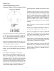
FIG. 22 THERMAL OVERLOAD
PROTECTOR TERMINALS
P1339
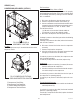
FIG. 21 COMPRESSOR START RELAY
TERMINALS
P1338
Model T-2155
Model T-2168
Removal and Replacement:
Compressor Start Relay: Refer to FIG. 20
1. Disconnect the wires from the compressor start re-
lay.
3. Pull relay (1) off of the compressor pins and discard.
4. Push new relay onto the compressor pins.
5. Refer to Fig. 21 and reconnect the wires.
6. Reinstall terminal cover (4) and cover retainer (5).
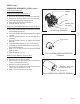
Compressor Run Capacitor: Refer to FIG. 20
1. Disconnect the run capacitor leads.
2. Remove the nut securing the run capacitor to the capaci-
tor mounting bracket.
3. Remove run capacitor and discard.
4. Place new run capacitor on capacitor mounting bracket
and secure nut.
5. Refer to Fig. 23 and reconnect the wires.
FIG. 23 COMPRESSOR RUN CAPACITOR
TERMINALS
P1816
White from Main Harness
Plug directly to two lower
terminals on Compressor
Black from Run Capacitor
White from Main Harness
Black from Run Capacitor
White from Main Harness
6. Install retainer (3) on new overload protector (2).
7. Install retainer (3) and overload protector (2) on the
compressor terminal bracket.
8. Refer to Fig. 22 and reconnect the thermal overload
protector wires.
9. Reinstall terminal cover (4) and cover retainer (5).
WHI/ORN from
Main Harness
BLK to Compressor
BLK to Start Relay T1
BLK to Start Relay T3
41084 102709