
Service and Repair Manual


40
SERVICE (cont.)
COMPRESSOR (APPLIANCES) (ULTRA-1) (cont.)
Compressor Assy:
NOTE: Before removal of any refrigeration component the
refrigerant in the system must be reclaimed by a licensed
refrigeration repair person.
NOTE: When replacing the compressor it is recommended
that the dryer also be replaced.
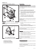
1. Disconnect the tubes from the condenser and the ac-
cumulator.
2. Disconnect the compressor wiring harness from the
dispenser main wiring harness.
3. Remove the four .25-20 keps nuts and washers securing
the compressor to the chassis. Set nuts and washers
aside for reassembly.
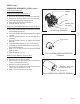
4. Disconnect and remove the transformer.
5. From the right side of the dispenser lift the compressor
assembly over the four studs in the chassis and remove
compressor.
6. Install new compressor over the four studs in the dis-
penser chassis with the fill valve to the right side of the
dispenser.
7. Secure compressor to the dispenser chassis using four
.25-20 keps nuts and washers.
8. Reconnect tubes from the condenser and the accumula-
tor to the compressor.
9. Reinstall transformer.
10. Evacuate the system.
11. Recharge 120V and 230V system with 6 oz. of Type
404A refrigerant.
Design Pressures: High 330 - Low 60
NOTE: The charging of the system must be done by a li-
censed refrigeration repair person.
NOTE: Refer to Wiring Diagrams when reconnecting wires
to Compressor, Thermal Overload Protector, Start Relay,
and Run Capacitor.
41084 021710