
Service and Repair Manual


43
R
SERVICE (cont.)
RELAY (or CONTACTOR on Early Models)
If continuity is present as described, disconnect the
dispenser from power source and reconnect wires to
terminals #6 and #8, the relay is working.
If continuity is not present as described, do the same
continuity test across terminals #2 and #4. If continu-
ity is present between terminals #2 and #4, reconnecr
wires to terminals #2 and #4 instead of #6 and #8.
If continuity is not present as described, replace the
relay.
Removal and Replacement:
1. Disconnect the wires from the relay.
2. Remove the two #8-32 locking screws securing the
relay to the chassis. Remove and discard relay.
3. Install the new relay on the chassis using two #8-32
locking screws.
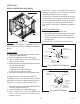
4. Refer to Fig. 33 and 34 to reconnect the wires.
FIG. 33 CONTACTOR TERMINALS
P1333
FIG. 32 RELAY
Location:
The relay (or contactor) is located inside the dis-
penser chassis on the lower outside of the component
bracket.
Test Procedures:
1. Disconnect the dispenser from the power source.
2. Remove the right side panel.
3. Connect the dispenser to the power source.
4. Turn on power (I/O) switch. Verify UPPER case
“ICE” or “CHILL” mode.
5. With a voltmeter, check the voltage across the white
wire and the orange wire.
The indication must be:
a) 120 volts ac for 120 volt models.
b) 230 volts ac for 230 volt models.
6. Disconnect the dispenser from the power source.
If voltage is present as described, proceed to #7.
If voltage is not present as described, refer to the Wir-
ing Diagram and check the dispenser wiring harness.
If harness has continuity, replace Control Board.
7. Disconnect the black wire and the WHI/ORN wires
from relay terminals #6 and #8.
8. Connect the dispenser to the power source.
9. Turn on power (I/O) switch. Verify UPPER case
“ICE” or “CHILL” and check for continuity across
terminals on relay.
Terminal #0
WHI from Main Harness
Terminal #1
ORN from
Control Board
Terminal #6
BLK from Main
Harness/Power Cord
Terminal #8
WHI/ORN from
Compressor Harness
Terminal #2
Terminal #4
ULTRA-2 shown
Early Model ULTRA-2
FIG. 34 RELAY TERMINALS
Terminal #0
WHI from
Main Harness
Terminal #1
ORN from
Main Harness
Terminal #6
WHI/ORN from
Main Harness
Terminal #8
BLK from
Main Harness
Terminal #2
Terminal #4
Late Model ULTRA-2 & ULTRA-1
41084 102709