
Service and Repair Manual


44
SERVICE (cont.)
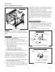
CONTROL BOARD
FIG. 35 CONTROL BOARD (ULTRA-2)
Removal and Replacement:
1. Disconnect the main harness from connector J5
(ULTRA-2) or J9 (ULTRA-1) on the control board.
2. Remove the four #8-18 pan head screws securing
the control board to the mounting box. Disconnect
TIC (memory) board from connector J1 on the
control board.
NOTE: On models with Auto-Fill, remove the auto-fill
adapter board.
3. Reconnect TIC board to J1 on the new control
board.
4. Secure the control board to mounting box with the
four #8-18 pan head screws.
5. Reconnect the main harness to J5 (ULTRA-2) or
J9 (ULTRA-1) on the control board.
Location:
The control board is located behind the front panel,
on the front of the chassis.
Test Procedures:
1. Disconnect the dispenser from the power source.
2. Remove the left and right side panels. Remove
the front panel and unplug ribbon cable from J5
(ULTRA-2) or J9 (ULTRA-1) .
3. With a voltmeter, check the supply voltage from
J5-8 (WHI/BLU) to J5-20 (WHI/BLK).
4. Connect the dispenser to the power source.
The indication must be:
Approximately 12.6 volts ac for all models.
5. Disconnect the dispenser from the power source.
If voltage is present as described and the dispenser
does not operate, replace Control Board.
If voltage is not present as described, refer to the Wir-
ing Diagram and check the dispenser wiring harness.
FIG. 36 CONTROL BOARD (ULTRA-1)
Control board
TIC board
Control board
TIC board
41084 102709