
Service and Repair Manual


46
1
2 3 4
5 6
7
SERVICE (cont.)
FAN - ULTRA-2
FIG. 39 FAN
Location:
The fan is located inside the dispenser chassis just
in front of the condenser.
Test Procedures:
1. Disconnect the dispenser from the power source.
2. Disconnect the gray and white wires from the main
harness to the fan leads.
3. With a voltmeter, check the voltage across the gray
and the white wires. Connect the dispenser to the
power source. In the “ICE” or “CHILL” mode;
The indication must be:
a) 120 volts ac for 120 volt models.
b) 230 volts ac for 230 volt models.
4. Disconnect the dispenser from the power source.
If voltage is present as described, replace the fan.
If voltage is not present as described, refer to Wiring
Diagram and check the dispenser wiring harness.
Removal and Replacement (Refer to Fig. 40)
NOTE: Leave the hopper in place. This keeps it in align-
ment while the condenser shroud is removed.
1. Disconnect the fan leads from the wiring har-
ness.
2. Remove the four #6 crimptite screws securing the
condenser shroud and fan assy (1) to the condenser
and the two #8-32 locking screws securing the
condenser shroud and fan assy (1) to the chassis
base.
3. Remove the condenser shroud and fan assy from
the right side of the dispenser.
4. Remove the three #6 thread cutting screws securing
the fan assy to condenser shroud (7). Set condenser
shroud and screws aside for reassembly.
5. Remove the three #8-32 thread forming screws
securing motor (5) to condenser fan shroud/mount
(6). Set shroud and screws aside for reassembly.
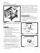
FIG. 40 FAN COMPONENTS
6. Remove speed nut (2) from the motor shaft.
7. Remove fan (3).
8. Remove silencer (4).
1. Condenser Shroud and Fan Assy
2. Speed Nut 3. Fan Blade
4. Silencer 5. Motor
6. Shroud/Mount 7. Condenser Shroud
9. Install silencer (4) on new motor assy.
10. Install fan (3) on new motor assy.
11. Install speed nut (2) on new motor assy.
12. Using three #8-32 thread forming screws secure
new motor assy to shroud/mount (6).
13. Using three #6-32 thread cutting screws secure new
motor and shroud/mount to the condenser shroud
(7).
14. Using two #8-32 locking screws secure condenser
shroud and fan assy (1) to the chassis base.
15. Using four #8-32 crimptite screws secure the con-
denser shroud and fan assy (1) to the condenser.
16. Refer to Fig. 41 and reconnect the leads on the new
motor to the dispenser wiring harness.
17. Use cable ties to secure wires away from fan
blades.
FIG. 41 FAN MOTOR TERMINALS
P1326
BLK to Main Harness WHI
BLK to Main Harness GRY
41084 102709