
Service and Repair Manual


47
SERVICE (cont.)
FAN - ULTRA-1
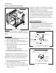
FIG. 42 FAN
Location:
The fan assembly is located inside the rear of the
dispenser chassis behind the condenser.
Test Procedures:
1. Disconnect the dispenser from the power source.
2. Connect a voltmeter across pins 1 and 2 of either
fan connector of the main wiring harness.
3. Connect the dispenser to the power source.
4. Turn on Power (I/O) Switch. Verify the dispenser
is in the “DAY” mode.
The indication must be:
a) 12 volts dc in the “DAY” mode,
b) 0 volts dc in the “NIGHT” mode.
If voltage is present as described, proceed to step 5.
If voltage is not present as described, refer to the Wiring
Diagrams and check the main wiring harness.
5. Check for continuity with an ohmmeter across the
red and black wires of the fan.
If continuity is present as described, the fan is operat-
ing properly.
If continuity is not present as described, replace the
fan.
6. Repeat test for other fan.
Removal and Replacement:
1. Disconnect the dispenser from the power source.
2. Remove the air filter from the back of the dis-
penser.
3. Remove the four #8-32 hex screws attaching the
fan and shroud assy to the condenser frame.
4. Disconnect the wiring harness from the fan being
replaced.
5. Remove the four screws attaching the fan to the
fan shroud and replace the fan.
6. Install the new fan such that the direction of air
flow matches that of the remaining fan. (arrow on
fan pointing toward condenser)
7. Reconnect the fan to the main wiring harness.
8. Install the fan and shroud assembly to the condenser
frame.
9. Replace the air filter and reconnect the dispenser
to power.
41084 102709