
Service and Repair Manual


48
SERVICE (cont.)
HOT GAS TEMPERATURE SENSOR
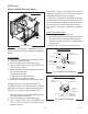
FIG. 43 HOT GAS SENSOR
Location:
The Hot Gas Sensor is located on the Condenser-
to-Compressor tube on the left side of the housing.
Test Procedures:
1. Remove the left side housing panel.
2. Connect a voltmeter, across the two leads of the
hot gas sensor (leave plug connected);
The indication must be:
a) Approx. 4.0 vdc @ 37° F
b) Approx. 3.4 vdc @ 82° F
If voltage reading is 0v, the Control Board is not sup-
plying the necessart 5v and should be replaced. If the
reading stays at 5vdc, replace the hot gas sensor.
Alternate Test:
2. Disconnect the plug on the hot gas sensor leads
from the connector on the main harness.
3. Connect an ohmmeter across the two leads of the
hot gas sensor;
The indication must be:
a) 678 ohms @ 212° F ± 10%
b) 10k ohms @ 77° F ± 10%
If resistance reading is not within the range listed above,
replace sensor.
Removal and Replacement (Refer to Fig. 43)
1. Remove the left side housing panel.
2. Disconnect the plug on the hot gas sensor leads
from the connector on the main harness.
3. Remove the clamp securing the hot gas sensor to
Condenser-to-Compressor tube.
4. Securing the new hot gas sensor to Condenser-
to-Compressor tube using the clampp previously
removed.
5. Refer to Fig. 44 and plug the new sensor into the
connector on the main harness.
FIG. 44 HOT GAS SENSOR
ULTRA-2 shown
ULTRA-2
1- WHI to YEL J5-10
(Control Board) Positive
2- WHI to WHI/BLK Main Harness/
J5-9 (Control Board) Negative
ULTRA-1
1- WHI to YEL J10-11
(Control Board) Positive
2- WHI to WHI/BLK Main Harness/
J10-15 (Control Board) Negative
2
1
41084 102709