
Service and Repair Manual


56
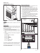
FIG.60 SOLENOID TERMINALS
SERVICE (cont.)
SOLENOIDS
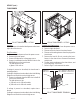
FIG. 59 SOLENOIDS
Location:
The solenoids are mounted on a bracket that is
attached to the front left corner of the chassis.
Test Procedures:
1. Disconnect the dispenser from the power source.
2. Remove the left side panel.
3. Connect a voltmeter across the white wire and the
other wire on the solenoid to be tested (output
from Control Board must be checked with load
connected).
4. Connect the dispenser to the power source.
5. Turn on the power (I/O) switch.
6. Verify that the side being tested is in the UPPER
case “ICE” or “CHILL” mode.
The indication must be:
a) 120 volts ac for 120 volt models.
b) 230 volts ac for 230 volt models.
7. Disconnect the dispenser from the power source.
If voltage is present as described, proceed to #8
If voltage is not present as described, refer to the Wir-
ing Diagram and check the main wiring harness.
8. Disconnect both wires and check for continuity
across the solenoid valve coil (Approximately 350
ohms).
If continuity is present as described, reconnect the
wires to the solenoid.
If continuity is not present as described, replace the
solenoids.
9. Repeat steps 4-6. If the cooling drum fails to
buildup a layer of frost, there may be a blockage
in the refrigerant line or solenoid. This will require
a licensed refrigeration repair person to evacuate
the system and make repairs as necessary.
NOTE: Before removal of any refrigeration component
the refrigerant in the system must be reclaimed by a
licensed refrigeration repair person.
Removal and Replacement:
1. Disconnect the wires from both solenoids.
2. Disconnect the refrigerant lines from the solenoids
to the cooling drums and the refrigerant line from
the filter/drier/splitter assembly.
3. Remove the #8-32 locking screw securing solenoid
bracket to the dispenser chassis.
4. Remove bracket and solenoids from the chassis
assembly.
5. Remove the two #6 crimptite screws securing the
solenoids to the bracket.
6. Remove solenoid and clean or discard.
7. Install new solenoids on mounting bracket using
two #6 crimptite screws.
8. Reinstall mounting bracket and solenoids inside the
dispenser chassis, securing with a #8-32locking
screw.
9. Reconnect the tubes from the accumulator and the
cooling drums.
10. Refer to Fig. 60 and reconnect the wires.
11. Evacuate the system.
12. Recharge the system with the appropriate coolant
and to the pressures directed on the decals.
NOTE: The charging of the system must be done by a
licensed refrigeration repair person.
ULTRA-2 shown
1. WHI from Main Harness
2. Left Coolant Solenoid (ULTRA-2)
BRN from Control Board J13-15
2. Right Coolant Solenoid (ULTRA-2)
RED from Control Board J13-16
2. Coolant Solenoid (ULTRA-1)
BRN from Control Board J10-19
2 1
41084 102709