
Service and Repair Manual


58
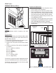
FIG. 64 TORQUE SENSOR CIRCUIT
BOARD TERMINALS
SERVICE (cont.)
TORQUE SENSOR CIRCUIT BOARD
FIG. 63 TORQUE SENSOR CIRCUIT BOARD
P1341
Location:
The torque sensor circuit board is located on the rear
of the cooling drum mount just left of center.
Test Procedures:
1. Place black meter lead at J1-3 (common) and red
lead at J1-1 (signal). Set meter to 10 - 20volts DC
scale. Turn on power switch.
DO NOT TURN ON AUGERS!
2. Using a strip of paper, momentarily block the light
path between red LED and white phototransistor.
If the meter displays 5vdc when blocked and 0v
when unblocked, then the Torque Sensor is good.
If there is no 5vdc reading, verify that both red and
white sensors are clean.
3. If there is still no 5vdc reading when blocked, place
the red meter lead at J1-2 and verify that there is
4.5vdc supplied to Torque Sensor. If there is no
5vdc supplied, check wiring between control board
and Torque Sensor. If wiring is ok, then replace the
main control board.
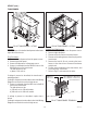
Removal and Replacement:
1. Remove the two #8-32 locking screws securing the
auger motor cover to the cooling drum mount.
2. Remove the cover and set aside for reassembly.
3. Remove the #8 locking screw on the lower right
side of the auger motor mounting bracket securing
the auger motor run capacitor. Set capacitor aside
with wires attached.
4. Disconnect the auger motor plug from the connector
on the main wiring harness.
5. Remove the three remaining #8 locking screws
securing the auger motor mounting bracket to
cooling drum mounting bracket.
6. Remove motor with mounting bracket, split pin/
torsion spring bearings as an assembly and set
aside for reassembly.
NOTE: When removing or installing the motor be sure
the split pin in the motor shaft is turned to a position
that will clear the torque sensor circuit board.
7. Disconnect the plug from the dispenser main wiring
harness to the torque sensor circuit board.
8. Remove the #8-32 locking screw and washer secur-
ing torque sensor circuit board to the cooling drum
mount.
9. Remove torque sensor circuit board and discard.
10. Install new torque sensor circuit board in the slot
in the rear of the cooling drum mount and secure
with a #8-32 locking screw and washer.
11. Refer to Fig. 42 and reconnect the wires.
12. Reinstall motor with mounting bracket, drip tray,
split pin and torsion spring bearings using three
#8 locking screws onto the cooling drum bracket.
13. Install the auger motor capacitor on the lower
right side of the auger mounting bracket using the
remaining #8 locking screw.
14. Connect the auger motor terminal to the terminal
on the main wiring harness.
15. Refer to Fig. 64 when reconnecting the wires.
16. Position the auger motor cover on the cooling
drum mount and secure with two #8-32 locking
screws.
J
1
1
1. Ultra-2 Left Signal (WHI/GRY)
1. Ultra-2 Right Signal (WHI/GRN)
1. Ultra-1 Signal (WHI/GRY)
2. (+) 5vdc (BLU)
3. (-) common (WHI/BLK)
L.E.D.
PHOTOTRANSISTOR
ULTRA-2 shown
41084 102709