
Service and Repair Manual


20
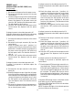
J2
J1
J3
J6
J7
SERVICE (cont.)
CONTROL BOARD and LEVEL PROBE (cont.)
Removal and Replacement:
1. Disconnect the dispenser from the power source.
2. Remove the two plugs (J1 and J7) from the main
wiring harness, the potentiometer plug (J3), the
photo transistor plug (J6), and the photo LED plug
(J2) from the control board.
3. Remove the four #6-32 keps nuts securing the con-
trol board to the hopper motor mounting panel.
4. Remove the control board.
5. Remove the four spacers from the old control board
and install them into the new control board.
6. Instal the new control board using the four #6-32
keps nuts.
7. Reconnect the two plugs (J1 and J7) from the
main wiring harness, the potentiometer plug (J3),
the photo transistor plug (J6), and the photo LED
plug (J2) to the control board. Refer to Fig. 12.
FIG. 12 CONTROL BOARD WIRING
P1905
41087.1 060112