
Service manual
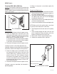
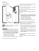
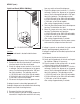
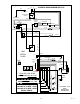
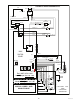
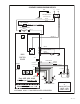
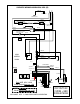

FIG. 10 THERMOSTAT WIRING
BLU/BLK to Limit Thermostat
BLK to Terminal Block
P1782
SERVICE (cont.)
Thermostat (H5M, HW2 & OHW Only)
Location: The mechanical thermostat is located inside
the upper rear panel. To test the thermostat, access will
also be needed to the terminal block located inside the
bottom access panel.
Test Procedure:
1. Disconnect the dispenser from the power source.
2. Check the voltage across the black wire on the
thermostat and the white or red wire at the terminal
block with a voltmeter. Connect the dispenser to the
power source. The indication must be:
a.) 100 to 120 volts ac for 100 to 120 volt models,
b.) 200 to 240 volts ac for 200 to 240 volt models,
c.) 230 volts ac for 230 volt models.
3. Disconnect the dispenser from the power source.
If voltage is present as described, proceed to #4.
If voltage is not present as described, refer to the Wiring
Schematics and check the dispenser wiring harness.
4. Check the voltage across the blue/black wire on
the thermostat and the white or red wire at the
terminal block with a voltmeter when the ther-
mostat is turned “ON” (fully clockwise). Connect
the dispenser to the power source. The indication
must be as described in step 2. Voltage must not
be indicated when the thermostat is turned “OFF”
(fully counterclockwise).
5. Disconnect the dispenser from the power source.
If voltage is present as described, the thermostat is
operating properly.
P1781
If voltage is not present as described, replace the
thermostat.
Removal and Replacement:
1. Remove both wires from the thermostat terminals.
2. Remove the top lid from the dispenser to gain ac-
cess to the thermostat bulb.
3. Remove the thermostat bulb by firmly pulling up on
the capillary tube at the tank. This will disengage
the grommet from the tank.
4. Remove the two #6-32 screws holding the thermo-
stat to the mounting bracket.
5. Fasten the new thermostat to the mounting bracket.
NOTE: Make sure that the capillary tube is away from
any electrical termination and is not kinked.
6. Slide the grommet to the red mark on the capillary
tube.
7. Insert the bulb through the hole in the tank and
press the grommet firmly and evenly so that the
groove in the grommet fits into the tank.
8. Refer to FIG. 10 when reconnecting the wires.
9. Readjust the thermostat dial as required.
FIG. 9 THERMOSTAT
(H5M SHOWN. HW2 & OHW SIMILAR)
42311 092414
21