
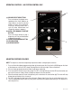
Installation and Operating Guide

6
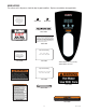
ELECTRICAL REQUIREMENTS
WARNING - The dispenser must be disconnected from the power source until specified in Initial Set-Up.
Refer to Data Plate on the Brewer, and local/national electrical codes to determine circuit requirements.
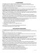
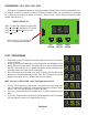
208 & 240 volt ac models
Note: This electrical service consists
of 2 current carrying conductors (L1
and L2) and a separate conductor for
earth ground.
220-240 volt ac (A)models
Note: This electrical service con-
sists of 2 current carrying conduc-
tors (L1 and Neutral) and a separate
conductor for earth ground.
120 volt ac models
Note: This electrical service con-
sists of 2 current carrying conduc-
tors (L1 and Neutral) and a separate
conductor for earth ground.
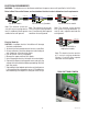
Electrical Hook-Up
CAUTION – Improper electrical installation will damage
electronic components.
1. An electrician must provide electrical service as specified.
2. Using a voltmeter, check the voltage and color coding of
each conductor at the electrical source.
3. Turn off master switch (if equipped).
4. Remove the upper and lower rear panels.
5. Install the proper electrical wiring to the terminal block.
6. Connect the dispenser to the power source and verify the
voltage at the terminal block before proceeding. Reinstall
both rear panels.
7. If plumbing is to be hooked-up later be sure the dispenser
is disconnected from the power source. If Plumbing has
been hooked-up, the dispenser is ready for Initial Set-Up.
WHITE
NEUTRAL
L1 BLACK
N
L1
G
POWER CORD
GREEN
WHITENEUTRAL
L1 BLACK
L2 RED L2 RED
L2
L1 BLACK
L1
G
POWER CORD
GREEN
L1 BLACK
N BLUE NEUTRAL BLUE
N
L1 BROWN
L1
G
POWER CORD
GREEN/YELLOW
L1 BROWN
46819.1 090916
120/208 & 120/240V ac
single phase models
Note: This electrical service consists
of 3 current carrying conductors
(Neutral, L1 and L2) and a separate
conductor for earth ground.
N
L1
G
L2 RED L2 RED
POWER CORD
WHITE
GREEN
NEUTRAL
L1 BLACK
WHITENEUTRAL
L2
L1 BLACK
DUAL VOLT TOGGLE SWITCH