C, CS, CT, CWTF, CRT, CRTF Series Including DV, MV, APS/TC/TS, Single CW & Twins Supercedes Service Manual: 41711.0000 SERVICE & REPAIR MANUAL BUNN-O-MATIC CORPORATION POST OFFICE BOX 3227 SPRINGFIELD, ILLINOIS 62708-3227 PHONE: (217) 529-6601 FAX: (217) 529-6644 41711.
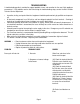
BUNN-O-MATIC COMMERCIAL PRODUCT WARRANTY Bunn-O-Matic Corp. (“BUNN”) warrants equipment manufactured by it as follows: 1) Airpots, thermal carafes, decanters, GPR servers, iced tea/coffee dispensers, MCP/MCA pod brewers thermal servers and Thermofresh servers (mechanical and digital)- 1 year parts and 1 year labor. 2) All other equipment - 2 years parts and 1 year labor plus added warranties as specified below: a) Electronic circuit and/or control boards - parts and labor for 3 years.
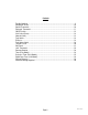
Contents Trouble Shooting �������������������������������������������������������������������������������������������������������������� 4 Component Access �������������������������������������������������������������������������������������������������������� 10 Control Thermostat �������������������������������������������������������������������������������������������������������� 10 Electronic Thermostat ���������������������������������������������������������������������������������������������������
TROUBLESHOOTING A troubleshooting guide is provided to suggest probable causes and remedies for the most likely problems encountered. If the problem remains after exhausting the troubleshooting steps, contact the Bunn-O-Matic Technical Service Department. • • • • • • • Inspection, testing, and repair of electrical equipment should be performed only by qualified service personnel. All electronic components have 120 volt ac and low voltage dc potential on their terminals.
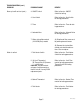
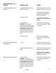
TROUBLESHOOTING (cont.) PROBLEM PROBABLE CAUSE REMEDY Brew cycle will not start (cont.) 3. ON/OFF Switch Refer to Service - ON/OFF Switch for testing. 4. Start Switch Refer to Service - Start Switch for testing procedures. 5. Timer Refer to Service - Timer for testing procedures. 6. Solenoid Valve Refer to Service - Solenoid Valve for testing procedures. 7. Water strainer/flow control (.222 GPM) Early models (A) Direction of flow arrow must be pointing towards brewer.
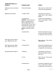
TROUBLESHOOTING (cont.) PROBLEM PROBABLE CAUSE REMEDY Inconsistent beverage level in dispenser 1. Strainer /flow control (.222 GPM) Early models. (A) Direction of flow arrow must be pointing towards the brewer. (B) Remove the strainer/flow control and check for obstruction. Clear or replace. Consistently low beverage level in the dispenser 2. Syphon System The brewer must be level or slightly lower in front to syphon properly. 3.
TROUBLESHOOTING (cont.) PROBLEM PROBABLE CAUSE REMEDY Spitting or excessive steaming (cont.) 2. Control Thermostat Refer to Service - Control Thermostat for testing procedures. Dripping from sprayhead 1. Syphon System The brewer must be level or slightly lower in front to syphon properly. 2. Lime Build-up CAUTION - Tank and tank components should be delimed regularly depending on local water conditions.
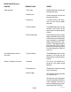
TROUBLESHOOTING (cont.) PROBLEM PROBABLE CAUSE REMEDY Weak beverage 1. Filter Type BUNN® paper filters must be used for proper extraction. 2. Coffee Grind A fine or drip grind must be used for proper extraction. 3. Sprayhead A six-hole stainless steel sprayhead must be used for proper extraction. 4. Funnel Loading The BUNN® paper filter must be centered in the funnel and the bed of ground leveled by gentle shaking. 5.
TROUBLESHOOTING (cont.) PROBLEM PROBABLE CAUSE REMEDY Brewer is making unusal noises (cont.) 4. Tank Heater Remove and clean lime off the tank heater. Low beverage serving temperature 1. Warmer Refer to Service - Warmer element for testing procedures. 2. ON/OFF Switch Refer to Service - ON/OFF Switch for testing procedures. Page 9 41711.
SERVICE This section provides procedures for testing and replacing various major components used in this brewer should service become necessary. Refer to Troubleshooting for assistance in determining the cause of any problem. WARNING - Inspection, testing, and repair of electrical equipment should be performed only by qualified service personnel. The brewer should be unplugged when servicing, except when electrical tests are required and the test procedure specifically states to plug-in the brewer.
SERVICE (cont.) OPTIONAL ELECTRONIC THERMOSTAT (ERT): The ERT is located inside the trunk on the upper left side of the component bracket. Test Procedures: 1. Disconnect the brewer from the power source. 2. Gently remove the temperature sensor and grommet from the tank. 3. Check voltage across the blue wire from limit thermostat and the white wire at the terminal block. Connect the brewer to the power source. The indication must be: 120Vac.
SERVICE (cont.) ON/OFF WARMER SWITCH Removal and Replacement: 1. Remove the wires from the switch terminals. 2. Compress the clips inside the hood and gently push the switch through the opening. 3. Push the new switch into the opening and spread the clips to hold switch in the hood. 4. Refer to Fig.7 when reconnecting the wires. FIG. 12-1 ON/OFF WARMER SWITCHES Location: The ON/OFF switch(s) are located on the front of the hood. (3) WHI to Neutral or RED to L2 (2) BLK to L1 Test Procedure: 1.
SERVICE (cont.) START SWITCHES Test Procedure: 1. Disconnect the brewer from the power supply. 2. Disconnect the blue wire and the white/red wire from the switch terminals. 3. Check for continuity across the two terminals on the switch when it is held in the "pressed-in" position. Continuity must not be present across these terminals in the released position. CT SERIES CRT/CRTF If continuity is present as described, reconnect the blue wire and the white/red to the switch terminals.
SERVICE (cont.) SOLENOID VALVES 6. Check the solenoid valve for coil action. Connect the brewer to the power source. With "ON/OFF" switch in the "ON' upper position press start switch and listen carefully in the vicinity of the solenoid valve for a" clicking" sound as the coil magnet attracts. 7. Disconnect the brewer from the power source.
SERVICE (cont.) SOLENOID VALVES Disassembly: 1. Use of the basin wrench 01060.0000 is recommended for disassembly of early style valves as illustrated below. 2. Disconnect from power source and turn off the water supply to the brewer. 3. Disconnect the water lines to and from the solenoid valve. 4. Remove the two #8-32 screws securing the solenoid mounting bracket to the component bracket. Remove solenoid bracket and solenoid valve as an assembly. 5.
SERVICE (cont.) FILL BASIN TANK HEATER FIG. 16-1 TANK HEATER FIG. 16-2 TANK HEATER Disassembly: 1. Use of the basin wrench 01060.0000 is recommended for removal of the fill basin. 2. Disconnect from power source and turn off the water supply to the brewer. 3. Remove top cover. 4. Use the basin wrench (as shown above) turning counterclockwise to remove inlet fitting. 5. Lift basin off of the tank inlet. 6. Use new inlet gasket when reinstalling.
SERVICE (cont.) TANK HEATER (Cont.) HEATER 1800W-120V 1850W-220V 3500W-200V 3500W-240V RESISTANCE 7.40 - 8.70 24.40 -28.40 10.70 15.36 -12.36 -17.90 TERMINAL TO SHEATH - INFINITE (OPEN) FIG. 17-1 TANK HEATER RESISTANCE If resistance is present as described, reconnect the wires, the tank heater is ok. If resistance is not present as described, replace the tank heater. NOTE- If any resistance is read between sheath and either terminal, remove and inspect heater for cracks in the sheath. 11.
SERVICE (cont.) TANK HEATER SWITCH 5. With the tank heater switch in the "ON" upper position, check for continuity between the black wire removed from the limit thermostat and the black insert on the terminal block. Continuity should not be present in the "OFF" lower position. If continuity is present as described, the tank heater switch is operating properly. If continuity is not present as described, replace the tank heater switch.
SERVICE (cont.) TANK HEATER SWITCH (cont.) 15. Set tank assembly inside the hood on mounting brackets and secure with two #8-32 screws. 16. Reconnect the wires to the limit thermostat, tank heater and the control thermostat. Refer to limit thermostat, tank heater and control thermostat sections in this manual when reconnecting wires. 17. Brewers with faucet reinstall the faucet tube and reconnect the water supply tube to the coil assembly. 18. Secure the sprayhead tube to the hood using hex nut. 19.
SERVICE (cont.) THERMAL CUT-OFF (Brewers W/Faucet) Removal and Replacement: 1. Disconnect both ends of the TCO. 2. Install new thermal cut-off. 3. Refer to Fig. 17 when reconnecting wires. Thermal Cut-Off from Tank Heater to BLK Lead from Control Thermostat WHI or RED to Terminal Block Fig. 20-1 THERMAL CUT-OFF Location: The thermal cut-off (TCO) is a thermal fuse located above the tank lid, connected to the tank heater. NOTE: Installed only on tanks with coil faucet.
SERVICE (cont.) COIL/FAUCET Location: The coil for the faucet is located in the tank. Operation: Water inside the coil is separate from the brewing water and is always under line pressure. Brewing water in the tank heats the submerged coil. Use of a coil faucet during a brew cycle will not cause short potting, but is limited to 8-10 ounces of hot water before the cooler water is passed through coil. Removal and Replacement: 1. Disconnect the brewer from the power and water sources. 2.
SERVICE (cont.) LIMIT THERMOSTAT If continuity is present as described, the limit thermostat is operating properly. If continuity is not present as described, replace the limit thermostat. Removal and Replacement: 1. Remove all wires from limit thermostat terminals. 2. Carefully slide the limit thermostat out from under the retaining clip and remove limit thermostat. 3. Carefully slide the new limit thermostat into the retaining clip. 4. Refer to the Fig. 5 when reconnecting the wires.
contact terminals. Connect the brewer to the power source. With the "ON/OFF" switch in the "ON" position and the start switch pressed and released, check for continuity across relay terminals. 7. Disconnect the brewer from the power source. RECOVERY BOOSTER RELAY (OPTIONAL) If continuity is present as described, reconnect the blue and black wires to the relay contact terminals. If continuity is not present as described replace the relay. B = COIL to TIMER 6-9 = N.O. spare A = COIL to TIMER 4-7 = N.O.
SERVICE (cont.) TIMER (Early Models) To Main Wiring Harness To Solenoid Valve EARLY STYLE FIG. 24-1 TIMER TERMINALS Location: The timer is located inside the front of the trunk on the upper right side of component bracket. Test Procedure. 1. Disconnect the brewer from the power source. 2. Disconnect the polarized, three pin connector from the brewer wiring harness. 3.
SERVICE (cont.) FRESHNESS TIMER (Early Models) If voltage is present as described, proceed to #4. If voltage is not present as described, refer to the Wiring Diagrams and check the brewer wiring harness. 4. Check the voltage across the T3 and T4 (white/ orange and white/blue wires) of the fresh timer with a voltmeter when the "ON/OFF" switch is in the "ON" position (upper) and start switch pressed. Connect the brewer to the power source.
SERVICE (cont.) DIGITAL BREW TIMER (Late Models) 4. With a voltmeter, check the output voltage across terminals TL2 and TL4 when the "ON/OFF" switch is in the "ON" position. Connect the brewer to the power source and press the "START" switch. The indication must be as follows: a) 120 volts ac for two wire 120 volt models and three wire 120/240 volt models. b) 200 to 240 volts ac for two wire 200 volt or 240 volt models. If voltage is present as described, the timer is operating properly.
SERVICE (cont.) DIGITAL BREW TIMER (Late Models)(cont.) Timer Setting: NOTE: Prior to setting or modifying volumes, check that the brewer is connected to water supply, the tank is properly filled, and a funnel and server are in place. NOTE: All volume settings must be done with the sprayhead installed. 1. Modifying brew volumes. To modify a brew volume, first check that the SET/LOCK switch is in the “SET” position on the circuit board.
SERVICE (cont.) WARMER ELEMENT(S) 4. Check the resistance across the two terminals on the warmer element. NOTE: There should be no resistance reading between the heater sheath and either terminal. Refer to the following chart. If resistance is to specification, reconnect the two wires to the warmer element. If resistance is not to specification, replace the warmer element. FIG. 28-1 WARMER ELEMENTS Location: The warmer element(s) is located under the warmer plate. Test Procedures: 1.
SCHEMATIC WIRING DIAGRAM CRT5, & CRTF5 L1 HEATER SWITCH BLK LIMIT THERMOSTAT BLK BLU SWITCH AND THERMOSTAT N GREEN (FAUCET OPTION ONLY) THERMAL CUT-OFF TANK HEATER BLK L2 WHI (MODEL 20) RED (MODEL 35) WHI WHI "KEEP WARM" HEATER ON/OFF SWITCH WHI WHI WHI/RED BLK LOWER CENTER WARMER START SWITCH WHI/RED BLU SOL WHI/RED WHI/BLU T1 T5 T3 BREW TIMER ON/OFF SWITCH BLK T4 T2 WHI/GRN WHI WHI YEL LEFT FRONT WARMER ON/OFF SWITCH WHI WHI WHI/VIO BLK LEFT REAR WARMER ON/OFF SWITCH WHI
SCHEMATIC WIRING DIAGRAM CRT5A, & CRTF5A L1 L2 GRN/YEL HEATER SWITCH BLK LIMIT THERMOSTAT BLU BLK (MODEL CRTF5A ONLY) THERMAL CUT-OFF BLK SWITCH AND THERMOSTAT TANK HEATER WHI RED WHI "KEEP WARM" HEATER ON/OFF SWITCH RED WHI/RED BLK RED LOWER CENTER WARMER START SWITCH WHI/RED SOL BLU WHI/RED WHI/BLU T1 T5 T3 T4 BREW T2 TIMER ON/OFF SWITCH BLK WHI/GRN RED RED YEL LEFT FRONT WARMER ON/OFF SWITCH RED RED WHI/VIO BLK LEFT REAR WARMER ON/OFF SWITCH BLK RED BRN/BLK RIGHT FRONT
SCHEMATIC WIRING DIAGRAM CRT5B, & CRTF5B L1 L2 GREEN HEATER SWITCH BLK LIMIT THERMOSTAT BLU BLK (MODEL CRTF5B ONLY) THERMAL CUT-OFF BLK SWITCH AND THERMOSTAT TANK HEATER ON/OFF SWITCH BLK WHI WHI WHI/RED WHI LOWER CENTER WARMER START SWITCH WHI/RED SOL BLU WHI/RED WHI/BLU T1 T5 T3 T4 BREW T2 TIMER ON/OFF SWITCH WHI/GRN WHI WHI YEL BLK LEFT FRONT WARMER ON/OFF SWITCH BLK WHI WHI WHI/VIO LEFT REAR WARMER ON/OFF SWITCH BLK WHI BRN/BLK RIGHT FRONT WARMER ON/OFF SWITCH BLK WHI WHI
L1 READY INDICATOR BLU BLK HEATER SWITCH LIMIT THERMOSTAT BLK BLK SW.
SCHEMATIC WIRING DIAGRAM CW-TS & CW-APS ERT THERMOSTAT SWITCH L1 HEATER SWITCH BLK BLK LIMIT THERMOSTAT BLU N L2 TAN WHI (FAUCET OPTION ONLY) THERMAL FUSE BLU BLK READY INDICATOR BLU WHI GRN TAN E.R.T ASSY.
SCHEMATIC WIRING DIAGRAM FOR CWT-APS MV, CWTF-APS MV, CWTF-TS MV, CWTF-TSR MV Page 34 41711.
Page 35 41711.
Page 36 41711.
Page 37 41711.
BLK Page 38 41711.
Page 39 41711.
GRN LT. READY INDICATOR BLK BLK LT.LIMIT THERMOSTAT LT. SW. & THERMOSTAT BLU SW1 MAIN ON/OFF SWITCH (Late Models only) BLK (FAUCET) THERMAL SAFETY FUSE BLK RED BLU BLK LEFT TANK HEATER BLK RED WHI WHI LEFT "KEEP WARM" HEATER RT. READY INDICATOR RED BLK BLK BLK RT. SW. & THERMOSTAT BLK RT.
GRN LT. READY INDICATOR BLK BLK LT.LIMIT THERMOSTAT LT. SW. & THERMOSTAT BLU SW1 MAIN ON/OFF SWITCH (Late Models only) BLK (FAUCET) THERMAL SAFETY FUSE BLK RED BLU BLK LEFT TANK HEATER BLK RED WHI WHI LEFT "KEEP WARM" HEATER RT. READY INDICATOR BLK BLK Models after 2/210 BLK RT. SW. & THERMOSTAT BLK RT.
SCHEMATIC WIRING DIAGRAM CWTFA TWIN 2/2 & 4/2 L1 LT. READY INDICATOR LEFT TANK HEATER BLK L3 RED LT. SW. & THERMOSTAT BLU (FAUCET) THERMAL SAFETY FUSE BLK BLK L2 GRN/YEL BLU LT. LIMIT THERMOSTAT SW1 BLU BLU RED WHI WHI LEFT "KEEP WARM" HEATER RT. READY INDICATOR BLK RIGHT TANK HEATER BLK BLK BLK RED RT. SW. & THERMOSTAT BLU BLK BLU RT.
SCHEMATIC WIRING DIAGRAM CWTFA & CWTFB TWIN 2/2 & 4/2 L1 LT. READY INDICATOR BLK BLK LT.LIMIT THERMOSTAT LT. SW. & THERMOSTAT BLU SW1 BLU L2 GRN/YEL BLK BLK RED (FAUCET) THERMAL FUSE BLK LEFT TANK HEATER RED RIGHT TANK HEATER RED RT. READY INDICATOR BLK BLK RT. LIMIT THERMOSTAT RT. SW.
SCHEMATIC WIRING DIAGRAM CWTFA 2/2 TWIN, CWTFA 4/2 TWIN & CWTFA TWIN-APS GRN/YEL LT. READY INDICATOR BLK BLK BLK LT. SW. & THERMOSTAT LEFT "KEEP WARM" HEATER BLK BLK BLK BLK RT. SW. & THERMOSTAT BLK RT. LIMIT THERMOSTAT SW2 BLU RIGHT "KEEP WARM" HEATER WHI RED WHI RT. READY INDICATOR RIGHT TANK HEATER LEFT TANK HEATER BLK BLU WHI (FAUCET) THERMAL SAFETY FUSE BLU SW1 BLK BLU LT.
SCHEMATIC WIRING DIAGRAM CWTFA TWIN-APS CE L1 LT. READY INDICATOR LT. SW. & THERMOSTAT SW1 BLK BLK BLU NC NC BLK WHI LT. TANK HEATER BLK LEFT "KEEP WARM" HEATER LT. LIMIT THERMOSTAT BLK BLU RED L2 GRN/YEL RED RED WHI LT. READY INDICATOR LT. SW. & THERMOSTAT SW2 BLK BLK BLU NC NC BLK WHI RT. TANK HEATER BLK RIGHT "KEEP WARM" HEATER RT.
GRN LT. READY INDICATOR BLU SW1 BLK BLK LT.LIMIT THERMOSTAT BLK BLU MAIN ON/OFF SWITCH (Late Models only) (FAUCET) THERMAL SAFETY FUSE LT. SW. & THERMOSTAT BLK BLK LEFT TANK HEATER BLK WHI SW2 BLK BLK WHI RT. LIMIT THERMOSTAT WHI BLK RT. SW. & THERMOSTAT BLU RIGHT TANK HEATER BLK WHI RED RED LEFT "KEEP WARM" HEATER RT.
L1 BLK-14 READY INDICATOR BLU BLK HEATER SWITCH BLK LIMIT THERMOSTAT BLK BLU SW.
SCHEMATIC WIRING DIAGRAM CWTB L1 BLU HEATER SWITCH BLK LIMIT THERMOSTAT BLK READY BLK SW. & THERMOSTAT (FAUCET OPTION ONLY) THERMAL FUSE BLK BLU L2 GRN/YEL BLK TANK HEATER RED ON/OFF SWITCH RED 3 BLK 2 1 WHI/RED WHI/RED RED LOWER WARMER OPTIONAL AUTOMATIC BREW CIRCUIT START SWITCH BLU WHI/RED P1 BLU/BLK P3 WHI/RED BLK P1, P2, & P3 ARE PINS OF A POLARIZED THREE-PIN CONNECTOR.
SCHEMATIC WIRING DIAGRAM CWTA L1 BLU HEATER SWITCH BLK LIMIT THERMOSTAT SW. & THERMOSTAT BLK L2 GRN/YEL (FAUCET OPTION ONLY) THERMAL FUSE BLK BLU BLK ON/OFF SWITCH READY TANK HEATER BLK RED WHI WHI "KEEP WARM" RED 3 BLK 2 1 WHI/RED WHI/RED RED LOWER WARMER OPTIONAL AUTOMATIC BREW CIRCUIT START SWITCH BLU WHI/RED P1 P3 WHI/RED SOL BLU/BLK BLK P1, P2, & P3 ARE PINS OF A POLARIZED THREE-PIN CONNECTOR.
SCHEMATIC WIRING DIAGRAM CWTA - CE READY INDICATOR BLU BLK L1 HEATER SWITCH BLK SW. & THERMOSTAT LIMIT THERMOSTAT BLK GRN/YEL L2 THERMAL FUSE BLK BLK BLU THERMAL FUSE RED RED TANK HEATER RED WHI BLK "KEEP WARM" HEATER WHI RED BLK ON/OFF SWITCH LOWER WARMER WHI/RED WHI/RED RED SOL OPTIONAL GRINDER INTERFACE BATCH SELECTION SWITCH 1 2 3 BREW 4 TIMER 5 P1, P2, & P3 ARE PINS OF A POLARIZED THREE-PIN CONNECTOR.
20 AMP T1 Page 51 T5 T3 T4 T2 41711.
L1 BLK-14 MAIN ON/OFF SWITCH (Late 20 & 35 Models only) RED Model 35 WHI Model 20 WHI Model 15 & 35 BLK GREEN BLK Model 15 SCHEMATIC WIRING DIAGRAM CWTF, CWTFB NO WARMER N L2 BLK Model 20 & 35 BLU HEATER SWITCH BLK BLK LIMIT THERMOSTAT BLK (FAUCET OPTION ONLY) THERMAL FUSE SW.
SCHEMATIC WIRING DIAGRAM CWTFA NO WARMER L1 READY INDICATOR BLU BLK LIMIT THERMOSTAT BLK BLU HEATER SWITCH THERMAL FUSE BLK BLK SW. & THERMOSTAT L2 GRN TANK HEATER THERMAL FUSE RED RED BLK RED BLK WHI WHI ON/OFF SWITCH BLK "KEEP WARM" HEATER RED WHI/RED WHI/ORA OPTIONAL AUTOMATIC BREW CIRCUIT START SWITCH OPTIONAL FRESH LIGHT SYSTEM GRY L.E.D. PNK BLK 4 INDICATOR 3 2 TIMER 1 WHI/RED WHI/RED BLU P3 P1, P2, & P3 ARE PINS OF A POLARIZED THREE-PIN CONNECTOR.
WHI GRN N L2 RED SCHEMATIC WIRING DIAGRAM CT-DV, CTF-DV, CWT-DV & CWTF-DV BLK L1 MAIN ON/OFF SWITCH (Late Models only) BLK READY INDICATOR BLU HEATER SWITCH LIMIT THERMOSTAT BLK BLK BLK SW.
WHI GRN SCHEMATIC WIRING DIAGRAM CWT, CWTF - APS, TS, TC DV N L2 RED BLK L1 MAIN ON/OFF SWITCH (Late Models only) BLK READY INDICATOR BLU HEATER SWITCH BLK LIMIT THERMOSTAT BLK BLK SW.
SCHEMATIC WIRING DIAGRAM SINGLE CW L1 BLK HEATER SWITCH BLK LIMIT THERMOSTAT BLK READY (FAUCET OPTION ONLY) THERMAL FUSE BLK SW.
GRN GRN RIGHT N L2 RED L1 BLK N WHI SCHEMATIC WIRING DIAGRAM CWTF TWIN 4/2 & 0/6 TWO-CIRCUIT WHI RED BLK LEFT L1 L2 READY INDICATOR BLK BLK LIMIT THERMOSTAT SW. & THERMOSTAT MAIN ON/OFF SWITCH (Late Models only) (FAUCET SIDE) THERMAL SAFETY FUSE TANK HEATER BLK BLK BLU WHI WHI "KEEP WARM" HEATER RED READY INDICATOR RED SW1-R BLK LIMIT THERMOSTAT BLK SW.
GRN SW1 BLK BLK LT. LIMIT THERMOSTAT LT. SW. & THERMOSTAT BLU BLU BLK BLU BLK BLK RT. LIMIT THERMOSTAT RED WHI LEFT "KEEP WARM" HEATER BLU BLK BLU BLK LEFT TANK HEATER K1 N.O. RT. SW. & THERMOSTAT BLU MAIN ON/OFF SWITCH (Late Models only) BLK WHI SW2 (FAUCET) THERMAL FUSE BLK RIGHT TANK HEATER RED BLK K2 N.O.
SCHEMATIC WIRING DIAGRAM CWTF TWIN 0/6 WITH RECOVERY BOOSTER L1 BLK BLU BLK BLK BLK BLU (FAUCET) THERMAL SAFETY FUSE BLK BLK LEFT TANK HEATER RED BLK K.1. N.O. WHI RT. READY INDICATOR LEFT "KEEP WARM" HEATER RED BLK RT. LIMIT THERMOSTAT BLK BLU BLU SW2 LT. SW. & THERMOSTAT BLU WHI L2 BLK RT. SW. & THERMOSTAT BLK BLK LT.LIMIT THERMOSTAT BLU SW1 N GREEN LT. READY INDICATOR RED BLU BLK BLU RIGHT TANK HEATER BLK RED BLK K.2. N.O.