
User Manual


Page 11
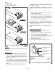
ON/OFF WARMER SWITCH
P1166.45
FIG. 4 ON/OFF WARMER SWITCH
SERVICE (cont.)
Location:
The ON/OFF warmer switch(s) are located on the
front of the hood.
Test Procedure:
1. Disconnect the brewer from the power source.
2. Viewing the switch from the back, remove the red
wire from the upper terminal and the black wire
from the center terminal.
3. With a voltmeter, check the voltage across the red
wire and the black wire. Connect the brewer to the
power source. The indication must be 220 to 240
volts ac.
4. Disconnect the brewer from the power source.
10860.1 091300
If voltage is present as described, reconnect the red
wire and proceed to #5.
If voltage is not present as described, refer to the
Wiring Diagrams
and check the brewer wiring har-
ness.
5. With the black wire removed, remove the wire
from the lower terminal.
6. Check for continuity across the center and lower
terminal with the switch in the "ON" (upper) posi-
tion. Continuity must not be present when the
switch is in the "OFF" (lower) position.
If continuity is present as described, reconnect the
black wire to the center terminal and the remaining
wire to the lower terminal.
If continuity is not present as described, replace the
switch.
Removal and Replacement:
1. Remove the wires from the switch terminals.
2. Remove front end cap.
3. Compress the clips inside the hood and gently
push the switch through the opening.
4. Push the new switch into the opening and spread
the clips to hold switch in the hood.
5. Reinstall front end cap.
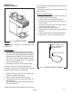
6. Refer to Fig. 5 when reconnecting the wires.
FIG. 5 ON/OFF WARMER SWITCH TERMINALS
P1918
ONE WARMER
TWO WARMERS
THREE WARMERS
RED to Terminal Block
(Red Insert)
BLK to Terminal Block
(Black Insert)
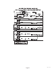
Terminal #1 (See Chart
Below)
Connect wire to Terminal #1 as follows:
Lower Warmer .................................................. WHI/RED
Rear Warmer ............................................................. VIO
Front Warmer ................................................... BRN/BLK