
User Manual


Page 14
P1167
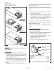
FIG. 11 WARMER ELEMENT TERMINALS
WARMER ELEMENT(S)
Location:
The warmer element(s) is located under the
warmer plate.
Test Procedures:
1. Disconnect the brewer from the power source.
2. With a voltmeter, check voltage across the red wire
to the terminal block and white/red, brown/black
or violet wire to the "ON/OFF" switch, with the "ON/
OFF" switch in the "ON" (upper) position. Connect
the brewer to the power source. The indication
must be 220 to 240 volts ac
3. Disconnect the brewer from the power source.
If voltage is present as described, proceed to #4.
If voltage is not present as described, refer to wiring
diagrams and check brewer wiring harness.
4. Remove the three #4-40 screws securing the
warmer assembly to the brewer.
5. Lift the warmer assembly from the brewer.
6. Disconnect the two wires from the warmer ele-
ment terminals.
7. Check the continuity across the two terminals on
the warmer element.
If continuity is present as described, reconnect the red
P1164
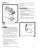
FIG. 10 WARMER ELEMENTS
SERVICE (cont.)
10860.1 091300
wire, and red/white, brown/black or violet wires on the
warmer element.
If continuity is not present as described, replace the
warmer element.
Removal and Replacement:
1. Remove the three #4-40 screws securing the
warmer assembly to the brewer.
2. Lift the warmer assembly from the brewer.
3. Disconnect the two wires from the warmer ele-
ment terminals.
4. Remove the two #8-32 nuts securing the warmer
element to the warmer plate.
5. Securly install new warmer element.
6. Reconnect the two wires to the warmer element
terminals.
7. Securly install warmer assembly on the brewer.
8. Refer to Fig. 11 when reconnecting the wires.
WHI/RED to ON/OFF Switch
BRN/BLK to ON/OFF Switch
VIO to ON/OFF Switch
RED to Terminal Block