BUNN ® 1SH & 2SH STAND OPERATING & SERVICE MANUAL BUNN-O-MATIC CORPORATION POST OFFICE BOX 3227 SPRINGFIELD, ILLINOIS 62708-3227 PHONE: (217) 529-6601 FAX: (217) 529-6644 28342.
WARRANTY Bunn-O-Matic Corp. (“Bunn”) warrants the equipment manufactured by it to be commercially free from defects in material and workmanship existing at the time of manufacture and appearing within one year from the date of installation. In addition: 1.) Bunn warrants electronic circuit and/or control boards to be commercially free from defects in material and workmanship for two years from the date of installation. 2.
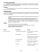
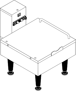
ELECTRICAL REQUIREMENTS The stands have an attached cordset and requires 2-wire grounded service rated 120 volts ac, single phase, 90 watts total for the 1SH, 180 watts total for the 2SH, or 2-wire grounded service rated 230 volts ac, single phase, 90 watts total for the 1SH, 180 watts total for the 2SH. CLEANING The use of a damp cloth rinsed in any mild, nonabrasive, liquid detergent is recommended for cleaning all surfaces on Bunn-O-Matic equipment.
SERVICE This section provides procedures for testing and replacing various major components used in these stands should service become necessary. Refer to Troubleshooting for assistance in determining the cause of any problem. WARNING - Inspection, testing, and repair of electrical equipment should be performed only by qualified service personnel.
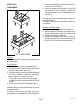
RECEPTACLE ASSEMBLY (SPRING CONTACT) SERVICE (cont.) Test Procedures 1. Disconnect the stand from the power source. 2. Remove the wires from the circuit breaker. 3. Check for continuity between the circuit breaker terminals. Continuity must be present between the terminals. If continuity is present as described the circuit breaker is functioning properly. If continuity is not present as described, press reset button and repeat step #3, if continuity is not present as described, replace the circuit breaker.
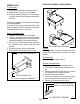
RECTIFIERS (cont.) SERVICE (cont.) RECTIFIER 1 2 3 4 5 6 Removal and Replacement: 1 Disconnect the wires from the rectifier. 2. Remove the #6-32 truss head screw securing the rectifier to the stand housing. 3. Remove the rectifier and discard. 4. Install new rectifier in the stand housing and secure with a #6-32 truss head screw. 5. Refer to Fig 7 and reconnect the wires. A + C A C FIG. 6 RECTIFIER FIG. 7 RECTIFIER TERMINALS P1403.
SERVICE (cont.) TRANSFORMER 5. Disconnet the blue/black wires from terminals #7 and #12 on the transformer. 6. Check the voltage across terminal #7 and #12 of the transformer with a voltmeter. Connect the stand to the power source. The indication must be 24 volts ac. 1 2 3 4 5 6 If voltage is present as described the transformer is operating properly. If voltage is not present as described, replace the transformer. 1 2 3 4 5 6 1 2 3 4 5 6 Removal and Replacement: 1.
SERVICE (cont.) TRANSFORMER (cont.
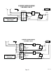
GRN N SCHEMATIC WIRING DIAGRAM 1 SH STAND – + L1 Front view of Server Contacts TRANSFORMER BLK 1 WHI 2 12 BLU/BLK 4 AMP BLU/BLK 24VDC BLK AC – RECT + AC 5 120 VOLTS AC, 2 WIRE SINGLE PHASE N L1 + – BLU/BLK BLU/BLK RED 7 6 SCHEMATIC WIRING DIAGRAM 2 SH STAND GRN – + Front view of Server Contacts TRANSFORMER 12 1 BLK BLU/BLK 2 WHI 4 AMP BLU/BLK AC – RECT + AC 24VDC 24VDC – – + + BLK 5 BLU/BLK BLU/BLK RED 7 6 TRANSFORMER 1 12 BLU/BLK 2 120 VOLTS AC, 2 WIRE SI
SCHEMATIC WIRING DIAGRAM 1 SH STAND, 230V CE L2 – + GRN/YEL L1 Front view of Server Contacts TRANSFORMER BRN 1 12 BLU 2 11 230 VOLTS AC, 2 WIRE SINGLE PHASE BLK 5 8 6 7 BLU/BLK 4 AMP BLU/BLK 24VDC AC – RECT + AC RESETTABLE FUSE BLU/BLK + – BLK BLU/BLK RED 27789.