SERVICE & REPAIR MANUAL BUNN-O-MATIC CORPORATION POST OFFICE BOX 3227 SPRINGFIELD, ILLINOIS 62708-3227 PHONE: (217) 529-6601 FAX: (217) 529-6644 39132.
BUNN-O-MATIC COMMERCIAL PRODUCT WARRANTY Bunn-O-Matic Corp. (“BUNN”) warrants equipment manufactured by it as follows: 1) Airpots, thermal carafes, decanters, GPR servers, iced tea/coffee dispensers, MCP/MCA pod brewers thermal servers and Thermofresh servers (mechanical and digital)- 1 year parts and 1 year labor. 2) All other equipment - 2 years parts and 1 year labor plus added warranties as specified below: a) Electronic circuit and/or control boards - parts and labor for 3 years.
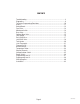
INTRODUCTION This equipment will brew a half-gallon batch of coffee into an awaiting dispenser. It can be easily configured for 120V 15 amp, 120/208V 20 amp or 120/240V 20 amp. The brewer may have a hot water faucet for allied beverage use. It is only for indoor use on a sturdy counter or shelf. CONTENTS Troubleshooting ..................................................................................................4 Diagnostics .............................................................................
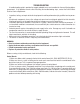
TROUBLESHOOTING A troubleshooting guide is provided to suggest probable causes and remedies for the most likely problems encountered. If the problem remains after exhausting the troubleshooting steps, contact the Bunn-O-Matic Technical Service Department. • • • • • • • Inspection, testing, and repair of electrical equipment should be performed only by qualified service personnel. All electronic components have ac line voltage and some have low voltage dc potential on their terminals.
TROUBLESHOOTING (cont.) REFILL CIRCUIT PROBLEM PROBABLE CAUSE REMEDY Will not refill 1. Power off to brewer Press OFF/ON switch on control panel to determine if power is ON. 2. Water shut off Make sure water is ON. 3. Error Message Brewer has shut down due to malfunction (See Diagnostic Section in this manual). 4.ON/OFF Switch (If equipped) Make sure ON/OFF Switch is "ON" and indicator is lit. 5. Lime build up on Probe(s) Remove the Level Probe(s) and check for lime deposit on tip.
TROUBLESHOOTING (cont.) HEATING CIRCUIT PROBLEM PROBABLE CAUSE REMEDY Water does not heat to proper temperature 1. Display's error message Brewer has shut down due to malfunction. See Diagnostics. 2. Water not touching main (short) level probe Remove level probe and grommet. Look into hole on tank lid. Water must be within approximately one inch from top of tank. 3. Water Level Probe Sensing System Check refill circuit. Heaters will not turn on if water is not grounding level probe. 4.
TROUBLESHOOTING (cont.) BREWING CIRCUIT PROBLEM Brew cycle will not start PROBABLE CAUSE 1. Display's error message REMEDY Brewer has shut down due to malfunction. See Diagnostics. 2. No water Water lines and valves to the brewer must be open. 3. No power or incorrect voltage to the brewer Check for voltage across the terminals at the terminal block. 4. ON/OFF switch not in the "ON" position The indicator lamp must be lit 5.
TROUBLESHOOTING (cont.) BREWING CIRCUIT (cont.) PROBLEM PROBABLE CAUSE REMEDY Dripping from sprayhead 1. Lime build up Inspect the tank assembly for excessive lime deposits. Delime as required. 2. Dispense valve Check/replace 1. Sprayhead A clean sprayhead must be used for proper extraction. 2. Water temperature Place an empty brew funnel on an empty decanter beneath the sprayhead. Initiate brew cycle and check the water temperature immediately below the sprayhead with a thermometer.
DIAGNOSTICS MESSAGE PROBABLE CAUSE REMEDY "CHECK SPRAYHEAD FOR LIME" "CHECK FITTINGS FOR LIME" 1. Lime buildup in sprayhead Clean sprayhead 2. Lime buildup in brew valve Clean valve 3. Lime buildup in brew tank Clean tank 1. Lime buildup in sprayhead Clean sprayhead 2. Lime buildup in brew valve Clean valve 3. Lime buildup in brew tank Clean tank 1. Lime buildup in sprayhead Clean sprayhead 2. Lime buildup in brew valve Clean valve 3. Lime buildup in brew tank Clean tank 1.
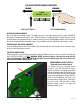
TECHNICIAN PROGRAMMING REMINDERS REVERSE FORWARD AXIOM VERSION VIEW ASSET/SERIAL # ##.## ENTER PROGRAMMING ACCESSING PROGRAM MODES Press and hold the right hidden switch. The longer you press it, the higher the level you can access. EXAMPLE: Pressing for a couple seconds enters Level 1. Continuing to press for approximately 5 seconds will access Level 2. Continue pressing for approximately 15 seconds to access Level 3.
COMPONENT ACCESS This section provides procedures for testing and replacing various major components used in this brewer should service become necessary. Refer to Troubleshooting for assistance in determining the cause of any problem. WARNING - Inspection, testing, and repair of electrical equipment should be performed only by qualified service personnel. The brewer should be unplugged when servicing, except when electrical tests are required and the test procedure specifically states to plug in the brewer.
5. Remove the two screws and two nylon washers securing the control board to the front face plate. 6. Tilt the control board inward to clear the display section. 7. Place the bottom edge of the new control board in the two cradles, tilt the board forward, and secure with the two screws and nylon washers to the front face plate. NOTE: The nylon washers must be installed under the heads of the two screws to prevent a possible shorting of the control board circuits. 8. Re-install wires & connectors.
FACEPLATE REMOVAL Faceplate Removal and Replacement: 1. Disconnect brewer from power source. 2. Disconnect the wires from the relay on the control board. 3. Disconnect the 10-pin connector (main harness) and the 3-pin connector (level probe harness) from the control board. 4. Disconnect the 10-pin connector (ribbon cable) from the control board. 5. Drain tank and disconnect/remove faucet. 6. Remove the 3 nuts and 1 standoff from back side of faceplate assembly. 7.
you can test it with an ohmmeter or continuity tester. Refer to the schematic to trace the appropriate pins. MEMBRANE SWITCH NOTE: Pin 1 is the static shield & will not provide a reading to the other pins. There are two commons in this circuit, pins 9 & 10. Disconnect brewer from power source before disconnecting ribbon cable from control board. FIG. 14-1 MEMBRANE SWITCH Removal and Replacement: 1. Disconnect the ribbon cable from 10-pin connector on the control board. 2.
BREW VALVE observed, brew valve is defective. Replace valve and test again to verify repair. If voltage is not present as described, refer to Wiring Diagrams and check the brewer wiring harness. Also check the control board and switch for proper operation. Removal and Replacement: 1. Disconnect the brewer from the power source. 2. Disconnect wires from the valve. 3. Drain enough water from the tank so the water level is below the outlet. 4. Remove hoses from the valve. 5.
OPTIONAL BREW VALVE (ON SELECT MODELS) observed, brew valve is defective. Replace valve and test again to verify repair. If voltage is not present as described, refer to Wiring Diagrams and check the brewer wiring harness. Also check the control board and switch for proper operation. Removal and Replacement: 1. Disconnect the brewer from the power source. 2. Disconnect wires from the valve. 3. Drain enough water from the tank so the water level is below the outlet. 4.
LEVEL PROBE SYSTEM 2. A high reading (approximately 255) indicates water is not touching, or not conductive enough to ground the circuit. A low reading (0-2) indicates the probe is grounded. Removal and Replacement: 1. Disconnect the brewer from the power source and allow tank to cool. 2. Remove nut, wire, and washers from probe. 3. Pull probe straight up from grommet. 4. When reinstalling, ensure long probe is connected to the blue wire, and short probe is connected to the brown wire.
If the sound is not heard as described, proceed to # 5. 5. Disconnect the brewer from the power source. 6. Check for continuity across the refill valve coil terminals. If continuity is not present as described, replace the refill valve. If continuity is present as described, there could be some debris in the valve. REFILL VALVE - EARLY MODELS FIG. 18-1 REFILL VALVE Location: The refill valve is located inside the front of the brewer. Test Procedures: 1.
REFILL VALVE - LATER MODELS FIG. 19-1 LATER REFILL VALVE # 5. 5. Disconnect the brewer from the power source. 6. Check for continuity across the refill valve coil terminals. If continuity is not present as described, replace the refill valve. If continuity is present as described, there could be some debris in the valve. Removal and Replacement: 1. Remove both wires from the refill valve. 2. Verify that the white shutoff clamp between valve and tank is squeezed shut. 3.
TANK HEATERS Location: The tank heaters are located inside the tank and secured to the tank bottom. Test Procedures: 1. With a voltmeter, check voltage across the white wire (120V Models) or red wire (120/208-240V Models) from the terminal block and black wire from the control board. Connect brewer to the power source. The indication must be 120 volts ac for two wire 120 volt models or 208-240 volts ac for three wire 120/208-240 volt models (during a heating cycle). 2.
LIMIT THERMOSTAT THERMAL CUT OFF (230V MODELS ONLY) FIG. 21-1 TCO CHECK Location: The TCO's are located under the tank at the heater connections. FIG. 21-2 LIMIT THERMOSTAT Location: The limit thermostat is located inside the top cover on the front side of the tank. Test Procedures: 1. Disconnect the brewer from the power source. 2. Disconnect the wires from the limit thermostat. 3. With an ohmmeter, check for continuity across the limit thermostat terminals. Test Procedures: 1.
BLANKET WARMER 4. Check the resistance across the two terminals on the blanket warmer. Refer to chart below. If resistance is to specification, reconnect the two wires to the blanket warmer. If resistance is not to specification, replace the blanket warmer. Removal and Replacement: 1. Disconnect the blanket warmer wire from the piggyback terminal on the refill valve. 2. Remove the tank assembly from the brewer. 3. Peel old blanket warmer off tank. 4.
TEMPERATURE PROBE If resistance is to specification, replace the control board. If resistance is not to specification, replace the temperature probe. Removal and Replacement: 1. Disconnect the brewer from the power source. 2. Disconnect the two pin connector from J9 on control board. 3. Pull temperature probe out of it's grommet. 4. Install in reverse order. FIG. 23-1 TEMPERATURE PROBE Location: The temperature probe is inserted through the tank lid assembly. Test Procedures: 1.
WARMER ELEMENTS wires to the warmer element. If resistance is not to specification, replace the warmer element. Removal and Replacement: 1. Remove the three #4-40 screws securing the warmer assembly to the brewer. 2. Lift the warmer assembly from the brewer. 3. Disconnect the two wires from the warmer element terminals. 4. Remove the two #8-32 nuts securing the warmer element to the warmer plate. 5. Securely install new warmer element. 6. Reconnect the two wires to warmer element terminals. 7.
VOLTAGE SELECTOR SWITCH Removal and Replacement: 1. Disconnect the brewer from the power source. 2. Disconnect the wires from the power switch. 3. Remove the switch mounting screws from the left side of trunk. 4. Install new switch in trunk with the two 6-32 x ¼˝ mounting screws. White to Term. Block-120V Position Blue to Tank Heater-Common WHI/VIO to Tank Heater 120/208-240V Position FIG.
MASTER ON/OFF SWITCH Removal and Replacement: 1. Disconnect the brewer from the power source. 2. Disconnect the wires from the power switch. 3. Remove the switch mounting screws from the left side of trunk. 4. Install new switch in trunk with the two 6-32 x ¼˝ mounting screws. FIG. 26-1 MASTER ON/OFF SWITCH Location: The rocker switch is located on the left side of the trunk behind the front access panel on some earlier models. The toggle switch on later models is located on the back of the trunk.
PROGRAMMING FUNCTIONS LEVEL 3 - FLOW CHART ENTERING LEVEL 3 REVERSE FORWARD AXIOM VERSION CAL TEMPERATURE % NO SENSOR? YES (-) SPRAY OZ/M: (-) DONE ##.# (+) ##.## LimeAdjust DONE OFF (+) CALIBRATE FLOW ? NO Page 27 YES LP1 LP2 OZ 4.50 (-) DONE (+) AXIOM VERSION ##.
PROGRAMMING - LEVEL 3 CAL TEMPERATURE NO SENSOR? YES Allows technician to calibrate after probe and/or control board replacement. Select "YES". NOTE: Tank temperature must be within range (192° - 208° F) VIDEO CLIP: Calibrate Temp Click - > 200° CAL 200° (-) DONE (+) % (-) LimeAdjust DONE OFF (+) LP1 LP2 OZ 4.50 (-) DONE SPRAY OZ/M: (-) DONE This screen allows adjustment of the lime compensation system when BrewLOGIC is turned on. Range: 2 - 50. Default: 10% variation of brewed volume.
PROGRAMMING FUNCTIONS LEVEL 4 - FLOW CHART ENTERING LEVEL 4 REVERSE FORWARD AXIOM VERSION SERIAL # TYPE (-) AX00 AX00 (+) (+) AX00000000 (-) DONE AXIOM AX00000000 SERIAL # TYPE (-) ##.## (+) (-) DONE (+) VERSION ##.## In case of board replacement, match the Data Plate information. AX00 - Standard Axiom with warmers AXAP - Axiom AirPot Server AXTN - Not used AXTS - Axiom Thermal Server EP00 - Engineering Prototype Scroll down (-) or up (+), to set the serial number of the machine.
Page 30 39132 041708 ALL MODELS EXCEPT TWINS
0/6 TWIN Page 31 39132 041708
4/2 TWIN Page 32 39132 041708
TWIN APS Page 33 39132 041708
MAIN ON/OFF SWITCH (Late 20 & 35 Models only) BLK-14 BLK Model 20 & 35 LIMIT THERMOSTAT BLU-14 BLK-14 WHI-14 Model 20 RED-14 Model 35 TANK HEATER BLK-14 N L2 RED Model 35 WHI Model 20 WHI Model 15 & 35 BLK L1 WHI Model 20 BLK Model 15 SCHEMATIC WIRING DIAGRAM GREEN AXIOM WHI Model 15 "KEEP WARM" HEATER WHI WHI BREW STATION WARMER WHI/RED (CONTROLLED BY ON/OFF SW) BLK WHI REFILL WHI/BLU DISPENSE # / .
Page 35 39132 041708
GRN N L2 WHI BLK L1 RED SCHEMATIC WIRING DIAGRAM AXIOM DV MAIN ON/OFF SWITCH (Late Models only) BLK BLK-14 SELECTOR SWITCH LIMIT THERMOSTAT BLU-14 BLK-14 TANK HEATER BLK-14 WHI-14 BLU-14 WHI TANK HEATER WHI/VIO-14 1425W "KEEP WARM" HEATER RED-14 2268W WHI BREW STATION WARMER (CONTROLLED BY ON/OFF SW) WHI/RED WHI REFILL WHI/BLU DISPENSE # / .
29077.0012 obsolete, refer to 29077.
Page 38 39132 041708 " / ! 2 $ # / . 4 2 / , 0 # J9 J3 J2 J1 1 2 3 1 10 5 1 10 5 1 COM N.O. TRM 1 TRM 2 BLK-18 BLK-14 WHI BLK BRN GRN BLU B1 A6 STATIC SHIELD WHI/GRN BLU-14 WHI/GRN D1 A3 D2 # / . 4 2 / , 0 ! A1 . % , A4 to D3 A5 B2 REAR FRONT HI W WHI WHI J9 J3 J2 J1 1 2 3 1 10 5 1 10 5 1 COM N.O.
Page 39 39132 041708 " / ! 2 $ # / . 4 2 / , 0 # J9 J3 J2 J1 1 2 3 1 10 5 1 10 5 1 COM N.O. TRM 1 TRM 2 BLK-18 BLK-14 WHI BLK BRN GRN BLU B1 STATIC SHIELD WHI/GRN BLU-14 D1 A3 D2 A4 to D3 A5 B2 (NOTE – ALL WARMERS ARE NOT AVAILABLE ON ALL MODELS!) SOL RIGHT LEFT P3 P2 P1 ! P1, P2, & P3 ARE PINS OF A POLARIZED THREE-PIN CONNECTOR J9 J3 J2 J1 1 2 3 1 10 5 1 10 5 1 COM N.O.
SCHEMATIC WIRING DIAGRAM AXIOM-APS N L1 GRN GRN/YEL Chassis Ground Chassis Ground Earth Ground RED BLK EMI FILTER BLK WHI MAIN POWER SWITCH LIMIT THERMOSTAT BLU-14 BLK-14 TANK HEATER BLK-14 WHI-14 "KEEP WARM" HEATER WHI WHI REFILL BLK WHI/BLU DISPENSE # / .
SCHEMATIC WIRING DIAGRAM AXIOM-APS L1 L2 GRN/YEL RED BLK EMI FILTER WHI BLK LIMIT THERMAL FUSE BLU-14 BLK-14 BLK-14 THERMOSTAT TANK HEATER THERMAL FUSE WHI-14 "KEEP WARM" HEATER WHI WHI WHI BLK REFILL WHI/BLU DISPENSE # / .
GRN WHI BLK SCHEMATIC WIRING DIAGRAM AXIOM DV-APS/TC N L2 RED L1 Earth Ground MAIN ON/OFF SWITCH (Late Models only) Chassis Ground BLK BLK-14 SELECTOR SWITCH LIMIT THERMOSTAT BLU-14 BLK-14 BLK-14 TANK HEATER WHI/VIO-14 1425W "KEEP WARM" HEATER WHI WHI-14 BLU-14 TANK HEATER RED-14 2268W WHI REFILL WHI/BLU DISPENSE # / .
L1 RED Model 35 WHI Model 20 WHI Model 15 & 35 BLK MAIN ON/OFF SWITCH (Late 20 & 35 Models only) BLK-14 BLK Model 20 & 35 LIMIT THERMOSTAT BLU-14 BLK-14 TANK HEATER BLK-14 N L2 WHI-14 Model 20 RED-14 Model 35 WHI Model 20 BLK Model 15 SCHEMATIC WIRING DIAGRAM SINGLE AXIOM - 15, 20 & 35 GREEN WHI Model 15 "KEEP WARM" HEATER WHI WHI BREW STATION WARMER WHI/RED (CONTROLLED BY ENABLE BREW SW) REFILL BLK WHI/BLU DISPENSE # / .
6&+(0$7,& :,5,1* ',$*5$0 $;,20 L1 L2 GRN/YEL RED BLK EMI FILTER WHI BLK LIMIT THERMAL FUSE BLU-14 BLK-14 TANK HEATER BLK-14 THERMOSTAT THERMAL FUSE WHI-14 "KEEP WARM" HEATER WHI WHI BREW STATION WARMER WHI/RED (CONTROLLED BY ON/OFF SW) BLK WHI WHI REFILL WHI/BLU DISPENSE # / .
Page 45 39132 061710 0 # " / ! 2 $ # / . 4 2 / , J9 J3 J2 J1 1 2 3 1 10 5 1 10 5 1 COM N.O. TRM 1 TRM 2 BLK-18 BLK-14 WHI BLK BRN GRN BLU B1 D1 A3 D2 A4 D3 B2 WHI/GRN t° WHI/BLU LEVEL PROBE (LONG) LEVEL PROBE (SHORT) # / . 4 2 / , 0 ! . % , SOL DISPENSE BLK-14 TANK HEATER L. Level Harness-p/n 39048.
SCHEMATIC WIRING DIAGRAM AXIOM TWIN APS/TC 100-200 VOLTS AC 230 VOLTS AC CE 2 WIRE + GND SINGLE PHASE 50-60 HZ L2 or N CONTROL SWITCH ASSY CODES Earth Ground RED or WHI BLK L1 MAIN ON/OFF SWITCH OPTIONAL RED or WHI BLK GRN or GRN/YEL Chassis Ground EMI FILTER Chassis Ground CE ONLY BLK BLK WHI WHI LIMIT THERMOSTAT LIMIT THERMOSTAT BLU-14 WHI C O N T R O L J1 P C B O A R D J2 BLK BLK COUNTER (OPTIONAL) COM N.O.
SCHEMATIC WIRING DIAGRAM AXIOM TS L1 L2 or N TERMINAL BLOCK MAIN ON/OFF SWITCH GRN/YEL BLK BLK WHI RED EMI FILTER WHI BLK LIMIT BLU-14 BLK-14 THERMOSTAT "KEEP WARM" HEATER WHI WHI BLK C O N T R O L P C B O A R D RELAY BLU-14 BLK-14 J1-1 WHI BLK THERMAL FUSE BLK-14 THERMAL FUSE TANK HEATER WHI-14 WHI REFILL J1-5 WHI/BLU WHI/BLU SOL WHI DISPENSE J1-10 WHI/GRN WHI/GRN WHI SOL CONTROL SWITCH ASSY STATIC SHIELD J2-1 J2-6 D1 B1 A3 D2 A4 D3 A7 B2 A2 A1 J2-10 CONTROL
Page 48 39132 021512 " / ! 2 $ # / . 4 2 / , 0 # J9 J3 J2 J1 1 2 3 1 10 5 1 10 5 1 COM N.O. TRM 1 TRM 2 BLK-18 BLK-14 WHI BLK BRN GRN BLU B1 A6 STATIC SHIELD WHI/GRN BLU-14 WHI/GRN D1 A3 D2 # / . 4 2 / , 0 ! A1 . % , A4 t° D3 A5 B2 P1, P2, & P3 ARE PINS OF A POLARIZED THREE-PIN CONNECTOR J9 J3 J2 J1 1 2 3 1 10 5 1 10 5 1 COM N.O.