DUAL™ TF DBC™ WITH SMART FUNNEL® S/N DUAL068000 & UP INSTALLATION & OPERATING MANUAL BUNN-O-MATIC CORPORATION POST OFFICE BOX 3227 SPRINGFIELD, ILLINOIS 62708-3227 PHONE: (217) 529-6601 FAX: (217) 529-6644 35058.0001A 07/05 ©2005 Bunn-O-Matic Corporation www.bunnomatic.
BUNN-O-MATIC COMMERCIAL PRODUCT WARRANTY Bunn-O-Matic Corp. (“BUNN”) warrants equipment manufactured by it as follows: 1) All equipment other than as specified below: 2 years parts and 1 year labor. 2) Electronic circuit and/or control boards: parts and labor for 3 years. 3) Compressors on refrigeration equipment: 5 years parts and 1 year labor.
TABLE OF CONTENTS User Notices ...............................................................................................................................4 Electrical .....................................................................................................................................5 Plumbing Requirements .............................................................................................................7 Operating Controls ......................................................
Page 4
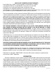
ELECTRICAL REQUIREMENTS (Models with power cord) WARNING - The brewer must be disconnected from the power source until specified in Initial Set-Up. Refer to Data Plate on the Brewer, and local/national electrical codes to determine circuit requirements.
ELECTRICAL REQUIREMENTS (Models without power cord) WARNING - The brewer must be disconnected from the power source until specified in Initial Set-Up. Refer to Data Plate on the Brewer, and local/national electrical codes to determine circuit requirements. 7()4% L1 BLACK .%542!, 200 or 230V , ",!#+ , 2%$ L2 RED GREEN , ",5% GREEN '2%%. '2%%.
PLUMBING REQUIREMENTS This brewer must be connected to a cold water system with operating pressure between 20 and 90 psi (138 and 620 kPa) from a 1⁄2" or larger supply line. A shut-off valve should be installed in the line before the brewer. Install a regulator in the line when pressure is greater than 90 psi (620 kPa) to reduce it to 50 psi (345 kPa). The water inlet fitting is 3⁄8" flare or female quick connect.
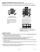
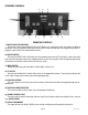
OPERATING CONTROLS h e d a a g c b f b c g OPERATING CONTROLS (a) BATCH SELECTOR SWITCHES Pressing the switch corresponding to the Small, Medium, or Large batch selects the amount of coffee to be brewed. Pressing a different switch after a brew cycle has been initiated does not change the brew batch in progress. Light indicates the selected batch to brew. (b) ON/OFF SWITCH Pressing the ON/OFF switch alternately turns the brewing side on and off.
INITIAL SETUP CAUTION – The brewer must be disconnected from the power source throughout the initial setup, except when specified in the instructions. 1. Insert an empty funnel into the funnel rails of one of the brew stations. 2. Place an empty server under the funnel. 3. Connect the brewer to the power source. Water will begin flowing into the tank and stop when the tank is filled to its capacity. Display will show PLEASE WAIT...TANK FILLING until tank is filled with water. 4.
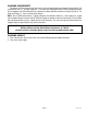
CLEANING 1. The use of a damp cloth rinsed in any mild, nonabrasive, liquid detergent is recommended for cleaning all surfaces on Bunn-O-Matic equipment. Do NOT clean this equipment with a water jet device. 2. Check and clean each sprayhead. The sprayhead holes must always remain open. NOTE: Any buildup on the sprayhead and fitting may restrict water flow, and impact your coffee brewing. For consistently great coffee, clean sprayheads and fittings weekly with sprayhead cleaning tool (#38227.0000).
GLOSSARY AD CARD: An assembly consisting of computer chips and an instruction label. Used for loading advertising messages into the brewer. BREW LOCKOUT: The inability to initiate a brew if the water temperature is less than the ready temperature programmed into the brewer. BYPASS: The process of diverting a portion of the brew water to the outside of the paper filter so that it does not pass through the coffee grounds. This process is sometimes used to optimize the flavor of the finished brew.
PROGRAMMING Using the menu-driven display on the front of the brewer, the operator has the ability to alter or modify various brewing parameters such as brew temperatures, brew volumes, bypass percentages, etc. This allows for the precise brewing of various flavors of coffee. Programming of the brewer is achieved by entering a certain function. Then, by the use of hidden programming switches, the operator can customize the brewing process to their specifications.
PROGRAMMING THE BREWER The programming of the brewer is divided into two levels. There is one function in Level 1. All other functions are accessed in Level 2. The following function screens are in order of appearance. Each screen will have instructions on how to access, and the procedures to program the various functions of the brewer. IMPORTANT PROGRAMMING NOTES - READ CAREFULLY To exit the programming mode at any time, press and release either of the ON/OFF switches located on the front switch panel.
PROGRAMMING THE BREWER (cont.) PROGRAM FUNCTIONS - LEVEL 2 There are three methods of programming the various brewing parameters of the Dual TF with Smart Funnel Brewer. METHOD 1: Using a Smart Funnel and a G9-2T DBC or MHG Grinder: Certain coffee NAMES are stored in the G9-2T DBC or MHG's memory. When a particular name of coffee is ground into the Smart Funnel, that name and the batch size selected are transferred from the grinder to the programming chip located in the funnel's handle.
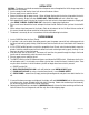
PROGRAM FLOW DIAGRAM LEVEL 1 Press upper right hidden switch for approximately 2 seconds, until the following screen appears. BREW LOCKOUT? NO DONE YES Returns to normal operating mode LEVEL 2 Press upper right hidden switch for approximately 4 seconds, until “UNITS” appears on screen.
(C) FULL 1/2 1/4 LEFT, SET ALL 3 BATCHES % BYPASS (-) DONE XX (+) RIGHT, SET ALL 3 BATCHES FULL 1/2 1/4 3 BATCHES DONE? NO YES SET PULSE BREW DRIP TIME X.
Page 17
PROGRAMMING THE BREWER (cont.) UNITS (SETTING UNITS OF MEASURE) This function allows the units of measure to be set in English or Metric readings for all screens. The program is defaulted to English. WARNING: Changing the unit of measure will erase all coffee recipes stored in memory. All preinfusion, pulse times, etc will also be erased. If using this option after information has been stored, it is important to have this information stored elsewhere so that the machine can be reprogrammed.
Page 19
PROGRAMMING THE BREWER (cont.) SET NEW RECIPES (cont.) 8. Using (-) and (+), set the amount of brew water, in ounces, to be dispensed for that particular batch size. 9. When finished, press another batch size and repeat step 8 for that size. Continue setting all batch sizes. 10. When finished setting all batch sizes, press and release DONE. The display should read 3 BATCH SIZES DONE? 11.
PROGRAMMING THE BREWER (cont.) SET NEW RECIPE Using a RECIPE CARD to load coffee names and brew settings into the Dual TF DBC with Smart Funnel: The G9-2T DBC or MHG's memory contains certain coffee names. If the operator uses a coffee name that is not already stored in the grinder's memory, a RECIPE CARD can be obtained from the factory. The RECIPE CARD would include all the information needed to set up that particular coffee name.
SET NEW RECIPE: If not using a Smart Funnel (with a sensor coil) and/or a G9-2T DBC or MHG Grinder, the brewer will function as a standard Bunn Dual TF Brewer: It is possible to operate the brewer without using a Smart Funnel and/or a G9-2T DBC or MHG Grinder. If a standard funnel, or if a non-DBC grinder is used the brewer will automatically select a NO NAME coffee flavor when the BREW switch is pressed. This means that no name was read from the funnel's handle.
PROGRAMMING THE BREWER (cont.) REVIEW RECIPES/MODIFY RECIPES/SET UP NO NAME COFFEE FLAVORS: This function has three parts. It allows the operator to view the brew settings for the various coffee names programmed into the brewer. It also allows the operator to modify (change) any of the BREW VOLUMES, BYPASS PERCENTAGES, PULSE BREW TIMES, PRE-INFUSION TIMES and DRIP-OUT TIMES for a particular coffee name programmed into the brewer.
PROGRAMMING THE BREWER (cont.) BREW OZ (SETTING OR ADJUSTING BREW VOLUMES) This function allows adjustment of the brew volumes for each batch. The indicator signifies volume in ounces per batch. Procedure for modifying recipes - brew ounces: Range: 10.0 oz to 400 oz for all three batch sizes 1. Press and hold the upper right hidden switch ® until the display reads UNITS. Release the switch, then press and release switch until the display reads REVIEW RECIPES. 2. Press YES to proceed.
PROGRAMMING THE BREWER (cont.) % BYPASS This function allows adjustment of the amount of water that bypasses the grounds. The number signifies the percentage of the brew volume which does not flow over the coffee grounds. Modifying recipes - bypass percentages: Range: 0% to 90% for all three batch sizes NOTE: If the brewer is already in the % BYPASS screen, it is not necessary to follow steps 1 through 6 in this section, but proceed directly to step 7. 1.
PROGRAMMING THE BREWER (cont.) SET PULSE BREW: This function allows the operator to program the brewer to "pulse” the sprayhead flow on and off during a brew cycle (start and stop the flow of water out of the sprayhead). This feature allows the ability to “fine-tune” the brewer for specific flavor profiles. Pulse brewing can be set up for any and all batches.
PROGRAMMING THE BREWER (cont.) SET PULSE BREW (cont.
PROGRAMMING THE BREWER (cont.) SET PULSE BREW - EASY PULSE SETUP NOTE: The procedure to enter the PULSE BREW function must be performed prior to following the steps listed below. 1. The display should read BREW TIME: X.XX and a batch size indicator will be flashing. 2. Using (-) and (+), set the desired brew time for the selected batch size. 3. When finished, select another batch size to be set by pressing the switch next to the indicator light. Repeat step 2 for each batch size to be set. 4.
PROGRAMMING THE BREWER (cont.) SET PULSE BREW - ENTER TIMES NOTE: The procedure to enter the PULSE BREW function must be performed prior to following the steps listed below. 1. Press and release YES. The display should now read EASY PULSE SETUP. 2. Press and release NO. The display will read ENTER TIMES? 3. Press YES to proceed. The display should now read 1st ON TIME X:XX. 4. Using (-) and (+) set the amount of time the flow of water into the funnel will be on. 5. When finished, press DONE.
PROGRAMMING THE BREWER (cont.) SET PREINFUSION: This function sets the brewer to turn the sprayhead flow on for a preset time (1st ON TIME) followed by a preset spray pause (OFF TIMES) and then turn the spray on continuously until the brew volume is completed. This is a special case of pulse brew. It is not possible to set a batch size to have both pulse brew and preinfusion. One or the other (or neither) must be chosen.
PROGRAMMING THE BREWER (cont.) DRIP TIME (now displayed on "non" funnel lock units as well) This function allows the setting or modification of the funnel locks to stay engaged after the end of a brew cycle. This ensures that the funnel cannot be removed until after the liquid has emptied out of the funnel. Procedure to modify drip times: Range: OFF to 10 minutes for all three batch sizes.
COPY SETTINGS (NO NAME COFFEE SETTINGS ONLY) This function is used to transfer all the brew settings from a NO NAME coffee flavor programmed on one side of the brewer to the other side. A NO NAME coffee is a flavor that is not in the grinder's memory or is what appears if a Smart Funnel® is not used.
PROGRAMMING THE BREWER (cont.) 2. Press YES in this screen. The display should read LEFT ->->-> RIGHT. 3. If the initial programming was done on the left side of the brewer, press YES. The display will read ARE YOU SURE? 4. If you are sure that the data should be transferred from left to right, press YES. The display will then read TRANSFER COMPLETE, and will automatically advance to the next function screen. 5.
PROGRAMMING THE BREWER (cont.) SET TEMP (cont.) 3. When finished, press and release DONE to save the new setting, exit the SET TEMP function and advance to the next function screen, SET READY. Another alternative is to press and release either ON/OFF switch located on the front switch panel to exit the SET TEMP function and return to the MAIN SCREEN. SET READY - Range: 185˚F (85˚C) to 203˚F (95˚C) This function allows the operator to set the minimum temperature allowable to start a brew cycle.
PROGRAMMING THE BREWER (cont.) Procedure to adjust the flow rate setting: 1. Press and hold upper right hidden switch until the display reads UNITS. Release switch. Continue to press and release switch until the display reads L SPRY OZ/M. The number represents what the brewer thinks is the flow rate of the sprayhead in ounces per minute. 2.
PROGRAMMING THE BREWER (cont.) CALIBRATE FLOW (cont.) and release either ON/OFF switch located on the front switch panel to exit the CALIBRATE FLOW function and return to the MAIN SCREEN. 9. Repeat steps 1 - 8 when calibrating the other side.
PROGRAMMING THE BREWER (cont.) BREW COUNTERS This function allows the operator to track the number of brew cycles completed on the left side, the right side, and the total of both combined. There are three resettable counters, and one life counter that is not resettable.
PROGRAMMING THE BREWER (cont.) BREW COUNTERS (cont.) 5. When finished, press NEXT to advance counter screens until the display reads BREW COUNTERS. Press and release NO to advance to the next function screen, or press and release either ON/OFF switch on the front switch panel to exit the BREW COUNTERS function and return to the MAIN SCREEN. FUNNEL DETECT (optional) This function allows the operator to prevent the start of a brew cycle if a Smart Funnel is not positioned correctly in the funnel rails.
PROGRAMMING THE BREWER (cont.) SERVICE TOOLS (cont.) Procedure to test components (outputs): 1. Place brew funnels into rails on both sides of brewer. 2. Place a server beneath each brew funnel. 3. Press and hold the upper right hidden switch until display reads UNITS. Release the switch. Continue to press and release switch until SERVICE TOOLS appears. 4. Press YES to run tests on various components and outputs within the brewer. Pressing NO will exit this function and advance to the next function screen.
PROGRAMMING THE BREWER (cont.) SERVICE TOOLS (cont.) 9. After all switches have been tested, press and release the right hidden switch (®). This will return to TEST SWITCHES?. Press and release switch again to advance to TEST SERVERS?. Another alternative is to press and release either ON/OFF switch located on the front switch panel. This will exit TEST SWITCHES and return to the MAIN SCREEN. FACTORY DEFAULTS This function allows the operator to erase all of the previously entered recipes and ad messages.
TROUBLESHOOTING A troubleshooting guide is provided to suggest probable causes and remedies for the most likely problems encountered. If the problem remains after exhausting the troubleshooting steps, contact the Bunn-O-Matic Technical Service Department. • • • • • • • WARNING • • • • Inspection, testing, and repair of electrical equipment should be performed only by qualified service personnel. All electronic components have 120 - 240 volt ac and low voltage dc potential on their terminals.
TROUBLESHOOTING (cont.) Screen Displayed TEMPERATURE TOO LOW Possible Cause Troubleshooting Procedures 1. Water temperature in the tank does not meet the SET READY TEMPERATURE. (a) Wait for the brewer to heat to the proper temperature. (b) Disable the BREW LOCKOUT function. CHECK FUNNEL FOR FRESH COFFEE 1. Brew funnel was not removed after the previous brew cycle was finished. Remove funnel, check contents, and insert back into the funnel rails.
TROUBLESHOOTING (cont.) Screen Displayed BREW STOPPED! IS SWITCH OFF? Possible Cause Troubleshooting Procedures 1. ON/OFF switch was pressed after the brew cycle was started. To resume brewing, press BREW again. The brew cycle resumes form the point it was interrupted. OR TO FINISH: PRESS BREW Press ON/OFF to terminate the brew cycle. TO CANCEL PRESS ON/OFF HEATING TIME TOO LONG 1. Tank Heater failure Service Required 2. Triac Failure Service Required 3.
TROUBLESHOOTING (cont.) Screen Displayed FILL TIME TOO LONG Possible Cause Troubleshooting Procedures 1. Water shut off to brewer Check water supply shut-off 2. Inlet Solenoid Valve failure Service required 3. Control Board Failure Service required 1. Temperature Sensor Probe wire(s) broken or not making connection. Check wire and connection of both black and white wires of temperature probe. 1. Temperature Sensor Probe wire(s) shorted to housing, or to each other.
TROUBLESHOOTING (cont.) Problem Possible Cause Troubleshooting Procedure Equipment will not operate. 1. No power or incorrect voltage. Measure the voltage at the terminal block and confirm that it matches the voltage specified on the brewer data plate within +/- 10%. Brew cycle will not start. 1. No water Check plumbing and shut-off valves 2. ON/OFF switch 3. Brew switch Test the BREW switch. Refer to the switch test procedures on page 33. 4. Brew Valve 5.
TROUBLESHOOTING (cont.) Problem Possible Cause Troubleshooting Procedure Automatic refill will not operate or display shows FILL TIME TOO LONG (cont.) 3. Refill Probe or Sensitivity Setting Check the sensitivity setting. Refer to the Refill function. If the left three digit number is less than the right number, the machine “thinks” it is full and the refill valve should be off. If the left number is larger than the right, then the refill valve will automatically be turned on to fill the tank.
TROUBLESHOOTING (cont.) Problem Possible Cause Troubleshooting Procedures Water flows into tank continuously with power applied to brewer. 1. Refill Probe or Sensitivity Setting Check the sensitivity setting. Refer to the Refill function. If the left three digit number is less than the right number, the machine “thinks” it is full and the refill valve should be off. If the left number is larger than the right, then the refill valve will automatically be turned on to fill the tank.
TROUBLESHOOTING (cont.) Problem Possible Cause Troubleshooting Procedures Water will not heat or display shows HEATING TIME TOO LONG (cont.) 3. Triac Remove power from the brewer. Connect a voltmeter across one of the tank heaters. Reapply power to the brewer and refer to Testing Individual Components. If the full supply voltage is measured when the tank heater is turned on, and zero voltage is measured with the triac off, then the triac is good.
TROUBLESHOOTING (cont.) Problem Possible Cause Troubleshooting Procedures Spitting or unusual steaming from sprayhead or air vents. (Water too hot) (cont.) 3. Electronic control board Perform the previous procedure for testing triacs. If the voltage measured is very low or zero, then substitute a control board known to be in good working order. Inconsistent beverage level in server. 1. Strainer (A) Direction of flow arrow must be pointing towards the brewer.
TROUBLESHOOTING (cont.) Problem Possible Cause Troubleshooting Procedures Consistently high or low beverage level in server. 1. Brew Volume adjustment Adjust the brew volume as required to achieve the recommended volume for each brew cycle. Dripping from sprayhead. 1. Brew Valve Repair or replace leaky valve. Water overflows filter. 1. Type of paper filters BUNN paper filters should be used for proper extraction. 2. No sprayhead Check sprayhead 1.
TROUBLESHOOTING (cont.) Problem Possible Cause Troubleshooting Procedures Weak beverage (cont.) 6. Incorrect Recipe Consider adjusting bypass percentage, preinfusion, or pulse brew. Contact Bunn-O-Matic for suggestions. Brewer is making unusual noises. 1. Solenoid (Inlet) The nut on back of the solenoid must be tight or it will vibrate during operation 2. Plumbing lines Plumbing lines should not be resting on the counter top. 3. Water Supply (A) The brewer must be connected to a cold water line.
SCHEMATIC WIRING DIAGRAM DUAL TF DBC BREWWISE L1 LIMIT THERMOSTAT BLK-14 L2 TRIAC MT 1 BLU-14 MT2 BLK-14 RIGHT TANK HEATER TRIAC LIMIT THERMOSTAT BLK-14 BLK-14 R E D 1 4 LEFT MT 1 BLU-14 MT2 N TANK HEATER SHIELD 1 C6 C5 C4 A4 B2 A3 B1 A2 A1 D3 C3 D2 L3 C2 D1 L8 C1 L7 L6 L5 L4 L1 L2 SWITCH UNIT ASSY 20 VIO SOL J4-19 J9-1 J4-15 J4-10 J4-1 J4-5 WHI/ORA LEFT FUNNEL SENSOR VIO J11-1 WHI/VIO WHI/GRN R. BYPASS SOL SOL ORA WHI L. BYPASS SOL WHI WHI R.
SCHEMATIC WIRING DIAGRAM DUAL TF DBC BREWWISE L1 BLK-14 BLK-14 RIGHT LIMIT THERMOSTAT LEFT LIMIT THERMOSTAT BLK-14 L2 RIGHT TANK HEATER BLK-14 R E D 1 4 L3 N B L U 1 4 BLU-14 N.O. LEFT TANK HEATER TRIAC MT1 BLU-14 MT2 BLK-14 RED-14 RED-14 CENTER LIMIT THERMOSTAT CENTER TANK HEATER BLU-14 BLU-14 BLU-14 N.O.
SCHEMATIC WIRING DIAGRAM DUAL TF DBC BREWWISE L2 GRN/YEL L1 RED BLK BLK RED EMI FILTER RED BLK BLK RED RIGHT LIMIT THERMOSTAT (1/2) BLK-14 BLK-14 LEFT LIMIT THERMOSTAT (1/2) BLK-14 BLK-14 TRIAC RIGHT LIMIT THERMOSTAT (1/2) R E D TANK HEATER 1 LEFT LIMIT 4 THERMOSTAT (1/2) LEFT MT1 BLU-14 MT2 RIGHT TRIAC MT 1 BLU-14 MT2 TANK HEATER SHIELD 1 C6 C5 C4 A4 B2 A3 B1 A2 D3 A1 C3 D2 L3 C2 D1 L8 C1 L7 L6 L5 L4 L1 L2 SWITCH UNIT ASSY 20 VIO SOL J4-19 J4-15 J4-5 J4-1
Page 55
SCHEMATIC WIRING DIAGRAM DUAL TF DBC, CE 3 PHASE W/NEUTRAL , , , . ,).% . % 3% 2 , ,/!$ . % 3% ,)-)4 ,)-)4 4 4!.+ ,)$ !3%-",9 ,)-)4 3 %4 2% , 4 3 %4 2% , % 3% , ",5 ",+ 2%$ , %-) &),4%2 (%!4%2 2 , '2. 4 (%!4%2 2 "2. 4%2-).!, ",/#+ 3 %4 2% 7IRE AS SHOWN FOR PHASE &OR SINGLE PHASE OPERATION MOVE RED WIRE IN TERMINAL BLOCK INTO CELL WITH BLACK WIRE APPLY POWER ACROSS , . (%!4%2 2%$ ",+ ",5 "2. #/.