CDBC TWIN CDBCF TWIN CDBC TWIN APS CDBCF TWIN APS N IO UT CA C A U T IO N : ! DISCONTINUED VERSION N IO ! CA UT The information in this manual is no longer current.
BUNN-O-MATIC COMMERCIAL PRODUCT WARRANTY Bunn-O-Matic Corp. (“BUNN”) warrants equipment manufactured by it as follows: 1) All equipment other than as specified below: 2 years parts and 1 year labor. 2) Electronic circuit and/or control boards: parts and labor for 3 years. 3) Compressors on refrigeration equipment: 5 years parts and 1 year labor.
CONTENTS Introduction & Warranty......................................................................................2 User Notices........................................................................................................3 Electrical & Plumbing Requirements....................................................................4 Operating Controls...............................................................................................5 Initial Set-Up, Coffee Brewing, & Cleaning............
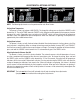
ELECTRICAL REQUIREMENTS CAUTION - The brewer must be disconnected from the power source until specified in Initial Set-Up. RED WHITE NEUTRAL BLACK GREEN 120/208 and 120/240 volt ac models L2 N 120 V.A.C. 208 or 240 V.A.C. 120 V.A.C. L1 GREEN Note: This electrical service consists of 3 current carrying conductors (Neutral, L1 and L2) and a separate conductor for earth ground. Refer to Data Plate on the Brewer, and local/national electrical codes to determine circuit requirements.
OPERATING CONTROLS CDBCA ENABLE ENABLE ON / OFF WARMER D B C ON / OFF BREW BREW WARMER WARMER A D B A WARMER C P1869 E N IO ! UT CA RY JU S IN SK Y RI MPL E TO ILUR FA CO A) ENABLE BREW ON/OFF SWITCH Pressing the "ON/OFF" switch (indicator glowing) supplies power to the brew station warmer, enables the brew circuit, and energizes the tank refill circuit. Pressing the switch again (indicator not glowing) stops tank refilling, brewing and deenergizes the brew station warmer.
1. 2. 3. 4. 5. 6. 7. 8. 9. INITIAL SET-UP Insert an empty funnel into the funnel rails of one of the brew stations. Place an empty decanter/server under the funnel. Connect the brewer to the power source. Press the "ON/OFF" switch (indicator glowing). Water will flow into the tank and stop when the tank is filled to its capacity. Wait approximately twenty minutes for the water in the tank to heat to the proper temperature. Place a small vessel beneath the faucet and open the faucet handle.
ADJUSTMENTS & OPTIONAL SETTINGS HIDDEN HIDDEN SWITCH SWITCH ENABLE ENABLE ON / OFF WARMER ON / OFF BREW BREW WARMER WARMER NOTE: The following adjustments must be performed for each Brew Station. WARMER P1871 Setting Brew Temperature The brewer is factory set to brew at 200°F(95°C). To change this setting, press and hold the "HIDDEN" switch beneath the "®". The word "TEMP" above the "ON/OFF" switch will glow to correspond with the temporary function change of this switch.
Adjusting brew volumes The brewer is factory set to deliver 64 ounces ± 2 for each brew cycle. BREW VOLUME SET-UP: Use the following steps when the setting is unknown or a different circuit board is being installed. 1. Place an empty funnel in the funnel rails and an empty decanter/server or graduated vessel beneath the funnel. 2. Press the "ON/OFF" switch (indicator glowing). 3. Press and hold the brew start button until you hear the brew solenoid click on-and-off three times (approximately 10 seconds).
PULSE BREW SETUP PROCEDURE The pulse brew parameters (initial fill time, off times, and remaining on times) are entered using the following set-by-example process. 1. First set the brew volume using the standard procedure in Brew Volume Setup. 2. Position an empty container under the sprayhead. Allow the tank to finish refilling. Make sure that the READY lamp is on, or that the BREW LOCKOUT function is turned off. 3. Press and hold the "ON/OFF" button. The brew valve will turn on after 10 seconds.
TROUBLESHOOTING A troubleshooting guide is provided to suggest probable causes and remedies for the most likely problems encountered. If the problem remains after exhausting the troubleshooting steps, contact the Bunn-O-Matic Technical Service Department. • • • • • • • Inspection, testing, and repair of electrical equipment should be performed only by qualified service personnel. All electronic components have 120 volt ac and low voltage dc potential on their terminals.
TROUBLESHOOTING (cont.) REFILL CIRCUIT PROBLEM PROBABLE CAUSE Will not fill or refill 1. Power off to brewer Press ON/OFF switch on control panel to determine if power is "ON". 2. Water shut off Make sure water is ON. 3. Display flashing Brewer has shut down due to malfunction (See Diagnostic Chart in manual, Page 20, or under top lid of brewer). 4. ON/OFF Switch Make sure ON/OFF Switch is "ON" and indicator is lit. 5. Lime build up on Probe Remove the Probe and check for lime deposit on tip.
TROUBLESHOOTING (cont.) REFILL CIRCUIT (cont.) PROBLEM Fill or refill does not shut "OFF" (ON/OFF Switch "OFF") PROBABLE CAUSE REMEDY 2. Water Level Probe Sensing System Disconnect the brewer from the power source. Disconnect the J3 connector from the control board. Check for continuity from the nut on top of the level probe to pin 1 of the plug, continuity should be present. Pull the temperature probe up about an inch from the grommet.
TROUBLESHOOTING (cont.) HEATING CIRCUIT PROBLEM PROBABLE CAUSE REMEDY Water does not heat to proper temperature 1. Display flashing Brewer has shut down due to malfunction (See Diagnostic Chart in manual, Page 20, or under top lid). 2. Water not touching temperature probe Remove probe and grommet. Look into hole on tank lid. Water must be within one inch from top of tank. 3. Dry Plug In Probe Sensing System Disconnect the brewer from the power source.
TROUBLESHOOTING (cont.) HEATING CIRCUIT PROBLEM PROBABLE CAUSE REMEDY Water does not heat to proper temperature (cont.) 4. Temperature Probe Remove the probe from the grommet and submerge in a water bath of approximately 70°F(21°C). Connect an ohmmeter to pins 3 and 4 of the J3 connector. At 60°F(16°C) the reading should be 15.3k ± 2k OHMS, at 70°F(21°C) the reading should be 11.8k ± 2k OHMS, and at 80°F(27°C) the reading should be 9.3k ± 2k OHMS.
TROUBLESHOOTING (cont.) HEATING CIRCUIT PROBLEM PROBABLE CAUSE REMEDY Spitting or excessive steaming (cont.) 2. Temperature Probe Remove the probe from the grommet and submerge in a water bath of approximately 70°F(21°C). Connect an ohmmeter to pins 3 and 4 of the J3 connector. At 60°F(16°C) the reading should be 15.3k ± 2k OHMS, at 70°F(21°C) the reading should be 11.8k ± 2k OHMS, and at 80°F(27°C) the reading should be 9.3k ± 2k OHMS.
TROUBLESHOOTING (cont.) BREWING CIRCUIT PROBLEM PROBABLE CAUSE REMEDY Brew cycle will not start 1. Display flashing Brewer has shut down due to malfunction (See Diagnostic Chart in manual, Page 20, or under top lid of brewer). 2. No water Water lines and valves to the brewer must be open. 3. No power or incorrect voltage to the brewer Check for voltage across the black and white terminals at the terminal block(s). 4. ON/OFF switch not in the "ON" position The indicator lamp must be lit 5.
TROUBLESHOOTING (cont.) BREWING CIRCUIT (cont.) PROBLEM PROBABLE CAUSE REMEDY Brew cycle will not start (cont.) 8. Control board or dispense valve If the switch panel is operating properly, proceed as follows. Attach a voltmeter to the terminals of the dispense solenoid. Connect the brewer to the power source. Turn on the brewer and press the BREW switch. Voltage should be present at the solenoid terminals. If voltage is not present, refer to the wiring diagrams and check the wiring harness.
TROUBLESHOOTING (cont.) BREWING CIRCUIT (cont.) PROBLEM PROBABLE CAUSE REMEDY Dripping from sprayhead 1. Lime build up Inspect the tank assembly for excessive lime deposits. Delime as required. 2. Dispense valve Remove the dispense valve and clear any obstructions. Rebuild or replace the valve if necessary. (See page 24) 1. Sprayhead A clean stainless steel sprayhead must be used for proper extraction. 2.
TROUBLESHOOTING (cont.) BREWING CIRCUIT (cont.) PROBLEM PROBABLE CAUSE REMEDY Dry coffee grounds remain in the funnel 1. Sprayhead Make sure sprayhead is present and holes are clear and unobstructed. There should be separate streams of water coming out of each hole in the sprayhead. 2. Funnel loading The BUNN paper filter must be centered in the funnel and the bed of grounds leveled by shaking gently. 1. Warmer Disconnect the brewer from the power source.
DIAGNOSTICS Intermittent flashing of the bank of temperature indicators indicates that a fault exists. Count the number of flashes between pauses and use this chart as a guide to investigating the fault.
SERVICE This section provides procedures for testing and replacing various major components used in this brewer should service become necessary. Refer to Troubleshooting for assistance in determining the cause of any problem. WARNING - Inspection, testing, and repair of electrical equipment should be performed only by qualified service personnel. The brewer should be unplugged when servicing, except when electrical tests are required and the test procedure specifically states to plug-in the brewer.
SERVICE (cont.) PC CONTROL BOARD N IO UT CA C A U T IO N : ! P1873 C A U T IO N : FIG. 2 CONTROL BOARDS Location: The Control Boards are located inside the top cover behind the front end caps. Test Procedures: The test procedures for the control boards will vary depending upon the problems experienced by the brewer. Refer to the Troubleshooting guide beginning on page 10. The troubleshooting guide is divided into three sections, Refill Circuit, Heating Circuit, and Brewing Circuit.
SERVICE (cont.) SWITCH PANEL N IO UT CA C A U T IO N : C A U T IO N : ! P1875 FIG. 3 SWITCH PANELS Location: The Switch Panels are located on the front of the hood. Removal and Replacement: 1. Disconnect the 11-pin connector to the switch panel from the control board. 2. Remove the four #6 screws, nylon washers and the two #4 screws securing the control board to the end cap assembly and set aside. 3. Gently pry the switch panel from the end cap assembly. 4.
SERVICE (cont.) DISPENSE VALVE 6. Connect the voltmeter lead ends to the dispense valve coil terminals. Connect the brewer to the power source. Brewer temperature lockout must be disabled. Place "ON/OFF" Switch in the "ON" position. Press and release the brew switch. The indication must be 120 volts ac for two-wire 120 volt models and three-wire 120/208 or 120/240 volt models. 7. Disconnect the brewer from the power source.
SERVICE (cont.) LIMIT THERMOSTAT J1 Removal and Replacement: 1. Remove the black and blue wires from limit thermostat terminals. 2. Carefully slide the limit thermostat out from under the retaining clip and remove limit thermostat. 3. Carefully slide the new limit thermostat into the retaining clip. 4. Refer to FIG. 7 when reconnecting the wires.
SERVICE (cont.) TANK HEATERS If continuity is present as described, reconnect the wires, the tank heater is operating properly. If continuity is not present as described, replace the tank heater. NOTE- If the tank heater remains unable to heat, remove and inspect heater for cracks in the sheath. FIG. 8 TANK HEATER P1855 Location: The tank heaters are located inside the tanks and secured to the tank bottoms. Test Procedures: 1. Disconnect the brewer from the power supply. 2.
SERVICE (cont.) TANK HEATERS (Cont.) 17. Install tank assembly onto mounting brackets and secure in place with four #8-32 nuts. 18. Install tank lid and secure in place with eight #8-32 nuts. 19. Connect the two white wires of the tank warmer blanket. 20. Connect the limit thermostat to the front of the tank assembly. 21. Connect the green wire to the tank mounting bracket using #8-32 nut. 22. Connect the pink wire to the level probe. 23.
SERVICE (cont.) REFILL VALVE J1 J2 J3 A R E H O T J5 U R F A C E S J4 W A R M E R S A N D S J1 C A U T IO N : J6 J7 J2 J3 J5 A R E H O T 6. Check the refill valve for coil action. Connect the brewer to the power source. With "ON/OFF" switch in the "ON' upper position press start switch and listen carefully in the vicinity of the refill valve for a" clicking" sound as the coil magnet attracts. 7. Disconnect the brewer from the power source.
SERVICE (cont.) WARMER ELEMENT(S) 5. Check the continuity across the two terminals on the warmer element. If continuity is present as described, reconnect the two wires to the warmer element. If continuity is not present as described, replace the warmer element. N UT IO CA C A U T IO N : C A U T IO N : ! FIG. 12 WARMER ELEMENTS P1875 Location: The warmer elements are located under the warmer plates. Removal and Replacement: 1.
Page 30 36672 020708 C O N T R O L P C B O A R D J5-1 J3-4 J3-1 J2-11 J2-6 J2-1 J1-10 J1-5 BLK BLK PNK GRN WHI COUNTER (OPTIONAL) BLU-14 STATIC SHIELD HIDDEN SW ON/OFF SW t LEVEL PROBE WHI/VIO YEL SOL REFILL W H I WHI WHI/BLU P1 WHI WHI WHI WHI P1, P2, & P3 ARE PINS OF A POLARIZED THREE-PIN CONNECTOR.
Page 31 36672 020708 C O N T R O L P C B O A R D J5-1 J3-4 J3-1 J2-11 J2-6 J2-1 J1-10 J1-5 BLK BLK PNK GRN WHI COUNTER (OPTIONAL) BLU-14 STATIC SHIELD HIDDEN SW ON/OFF SW t° LEVEL PROBE TOP FRNT SW REFILL C O N T R O L P C B O A R D LIMIT THERMOSTAT BLU-14 L1 WHI VIO TOP FRONT WARMER SOL 120/208V AC 3 WIRE + GND 120/240V AC 3 WIRE + GND SINGLE PHASE P3 WHI/GRN DISPENSE WHI WHI WHI WHI P1, P2, & P3 ARE PINS OF A POLARIZED THREE-PIN CONNECTOR.
Page 32 36672 020708 C O N T R O L P C B O A R D J3-4 J3-1 J2-11 J2-6 J2-1 J1-10 J1-5 COUNTER (OPTIONAL) BLU-14 BLK PNK GRN WHI STATIC SHIELD HIDDEN SW ON/OFF SW t° LEVEL PROBE LEFT CONTROL PANEL ASSY BREW SW WHI/GRN WHI/BLU BLK J1-1 BLK J1-2 BLU-14 COM BLK-14 N.O.
Page 33 36672 020708 BREW J2 J1 1 10 5 1 J5 J3 STATIC SHIELD PROGRAM 4 1 4 1 10 ENABLE BREW 5 TOP FRONT P C B O A R D C O N T R O L COM N.O. TRM 1 TRM 2 BLK-18 BLK-14 BLK BLK PNK GRN WHI BLU-14 WHI/GRN t˚ LEVEL PROBE REFILL SOL RIGHT LEFT HI W P3 P2 P1 (TOP WARMERS) W EL Y /V N BREW J2 J1 1 10 5 1 J5 J3 STATIC SHIELD PROGRAM 4 1 4 1 10 ENABLE BREW 5 TOP FRONT P C B O A R D C O N T R O L COM N.O.
Page 34 36672 020708 BREW J2 J1 1 10 5 1 COM N.O. J5 J3 4 1 4 1 PROGRAM TOP REAR TOP FRONT 10 STATIC SHIELD ENABLE BREW 5 P C B O A R D C O N T R O L TRM 1 TRM 2 BLK-18 BLK-14 BLK BLK PNK GRN WHI BLU-14 WHI/GRN t˚ LEVEL PROBE REFILL SOL REAR FRONT HI W (TOP WARMERS) /V W EL Y Main Harness p/n 40666.0001 Warmer Harness p/n 24204.0000 WHI WHI WHI WHI WHI WHI N BREW J2 J1 1 10 5 1 COM N.O.
Page 35 #/.42/, 0# "/!2$ 10 5 1 J5 J3 STATIC SHIELD PROGRAM 4 1 4 1 10 1 BREW LEFT FRONT LEFT REAR ENABLE BREW 5 J2 J1 COM N.O. TRM 1 TRM 2 BLK-18 BLK-14 WHI/GRN PROBE CLIPp/n 34813.0000 BLK BLK GRN WHI t˚ LEVEL PROBE RED/BLK REFILL SOL REAR HI W L1 BLK Main Harness p/n 40666.0000 N 1 10 5 1 J5 J3 4 1 4 1 PROGRAM RIGHT REAR RIGHT FRONT 10 STATIC SHIELD ENABLE BREW 5 BREW J2 J1 COM N.O.