CDBC, CDBCF CDBCP, CDBCFP S/N CDBC020213 & up SINGLE CD, SINGLE CDF N IO UT CA DISCONTINUED VERSION The information in this manual is no longer current. OPERATING & SERVICE MANUAL BUNN-O-MATIC CORPORATION POST OFFICE BOX 3227 SPRINGFIELD, ILLINOIS 62708-3227 PHONE: (217) 529-6601 FAX: (217) 529-6644 35582.0000C 02/04 ©2003 Bunn-O-Matic Corporation www.bunnomatic.
INTRODUCTION This equipment will automatically brew a half-gallon batch of coffee into an awaiting decanter at the press of a button. A hot water faucet is included for allied beverage use. Most functions of the brewer are digitally controlled. It is only for indoor use on a sturdy counter or shelf. CONTENTS Introduction & Warranty .................................................................................................................. 2 User Notices ................................................
USER NOTICES Carefully read and follow all notices in this manual and on the equipment. All labels on the equipment should be kept in good condition. Replace any unreadable or damaged labels. # 00986.0000 ! WARNING DO NOT OVERLOAD CIRCUIT. ALWAYS ELECTRICALLY GROUND THE CHASSIS OR ADAPTOR PLUG. DO NOT DEFORM PLUG OR CORD. FOLLOW NATIONAL AND LOCAL ELECTRICAL CODES. KEEP COMBUSTIBLES AWAY. FAILURE TO COMPLY RISKS EQUIPMENT DAMAGE, FIRE OR SHOCK HAZARD.
ELECTRICAL REQUIREMENTS CAUTION - The brewer must be disconnected from the power source until specified in Initial Set-Up. Model 15 has an attached cordset and requires 2-wire grounded service rated 120 volts ac, 15 amp, single phase, 60 Hz. L2 RED WHITE NEUTRAL L1 BLACK WHITE 120V.A.C. 120V.A.C. 208 or 240V.A.C. NEUTRAL 120V.A.C. L1 BLACK Model 20 requires 2-wire, grounded service rated 120 volts ac, 20 amp, single phase, 60 Hz.
OPERATING CONTROLS ON/OFF SWITCH Pressing the "ON/OFF" switch (indicator glowing) supplies power to the brew station warmer, enables the brew circuit, and energizes the tank refill circuit. Pressing the switch again (indicator not glowing) stops tank refilling and brewing and deenergizes the brew station warmer. Stopping a brew cycle after it has been started will not stop the flow of water into the decanter until the funnel is empty.
INITIAL SET-UP 1. 2. 3. 4. Insert an empty funnel into the funnel rails. Place an empty decanter under the funnel. Connect the brewer to the power source. Model CDBC – Press the "ON/OFF" switch (indicator glowing). Model SINGLE CD - Press the "1 gal" switch (indicator glowing) and the "ON/OFF" switch (indicator glowing). 5. Water will flow into the tank and stop when the tank is filled to its capacity. 6. Wait approximately twenty minutes for the water in the tank to heat to the proper temperature. 7.
POUR-OVER FEATURE Models CDBCP & CDBCFP If the brewer is equipped with a pour-over feature, follow the instructions below. 1. Remove the thumbscrew and pour-in lid from the top cover of the brewer and set aside. 2. Insert a BUNN® filter into the funnel. 3. Pour fresh coffee grounds into the filter and level the bed of grounds by gently shaking. 4. Slide the funnel into the funnel rails. 5. Place an empty decanter beneath the funnel. 6.
CDBC, SINGLE CD ADJUSTMENTS & OPTIONAL SETTINGS HIDDEN SWITCH P1866 Setting Brew Temperature The brewer is factory set to brew at 200°F (93˚C). To change this setting, press and hold the "HIDDEN" switch beneath the "®". The word "TEMP" above the "ON/OFF" switch will glow to correspond with the temporary function change of this switch. Repeatedly press and release the "ON/OFF" switch until one of the bank of temperature indicators shows the approximate desired temperature.
ADJUSTMENTS & OPTIONAL SETTINGS (cont.) BREW VOLUME SET-UP: Use the following steps when the setting is unknown or a different circuit board is being installed. 1. Place an empty funnel in the funnel rails and an empty decanter/server or graduated vessel beneath the funnel. 2. Place the "ON/OFF" switch in the "ON", upper position. 3. Press and hold the brew start button until you hear the brew solenoid click on-and-off three times (approximately 10 seconds). Release the button. 4.
PULSE BREW SETUP PROCEDURE (CDBC & SINGLE CD) The pulse brew parameters (initial fill time, off times, and remaining on times) are entered using the following setby-example process. 1. First set the brew volume using the standard procedure in Brew Volume Setup. 2. Position an empty container under the sprayhead. Allow the tank to finish refilling. Make sure that the READY lamp is on, or that the BREW LOCKOUT function is turned off. 3. Press and hold the OFF/ON button.
TROUBLESHOOTING A troubleshooting guide is provided to suggest probable causes and remedies for the most likely problems encountered. If the problem remains after exhausting the troubleshooting steps, contact the Bunn-O-Matic Technical Service Department. • • • • • • • Inspection, testing, and repair of electrical equipment should be performed only by qualified service personnel. All electronic components have 120 volt ac and low voltage dc potential on their terminals.
TROUBLESHOOTING (cont.) REFILL CIRCUIT PROBLEM PROBABLE CAUSE REMEDY Will not fill or refill 1. Power off to brewer Press warmer switches on control panel to determine if power is ON. 2. Water shut off Make sure water is ON. 3. Display flashing Brewer has shut down due to malfunction (See Diagnostic Chart in manual, Page 21, or under top lid of brewer). 4. ON/OFF Switch Make sure ON/OFF Switch is "ON" and indicator is lit. 5.
TROUBLESHOOTING (cont.) REFILL CIRCUIT (cont.) PROBLEM PROBABLE CAUSE REMEDY Fill or refill does not shut "OFF" (ON/OFF Switch "ON") 1. Lime build up on probe Remove Probe and check for lime deposits on tip. Clean and reinstall. 2. Water Level Probe Sensing System Disconnect the brewer from the power source. Disconnect the J3 connector from the control board. Check for continuity from the nut on top of the level probe to pin 1 of the plug, continuity should be present.
TROUBLESHOOTING (cont.) HEATING CIRCUIT PROBLEM Water does not heat to proper temperature IMPORTANT: Make sure no temperature tests are taken before the ready light is "ON". Tank temperature must be stabilized before readings are taken. PROBABLE CAUSE REMEDY 1. Display flashing Brewer has shut down due to malfunction (See Diagnostic Chart in manual, Page 21, or under top lid). 2. Water not touching temperature probe Remove probe and grommet. Look into hole on tank lid.
TROUBLESHOOTING (cont.) HEATING CIRCUIT (cont.) PROBLEM Water does not heat to proper temperature (cont.) PROBABLE CAUSE REMEDY 4. Temperature Probe Remove the probe from the grommet and submerge in a water bath of approximately 70°F(21°C). Connect an ohmmeter to pins 3 and 4 of the J3 connector. At 60°F(16°C) the reading should be 15.3k ± 2k OHMS, at 70°F(21°C) the reading should be 11.8k ± 2k OHMS, and at 80°F(27°C) the reading should be 9.3k ± 2k OHMS.
TROUBLESHOOTING (cont.) HEATING CIRCUIT (cont.) PROBLEM PROBABLE CAUSE REMEDY Spitting or excessive steaming (cont.) 2. Temperature Probe Remove the probe from the grommet and submerge in a water bath of approximately 70°F(21°C). Connect an ohmmeter to pins 3 and 4 of the J3 connector. At 60°F(16°C) the reading should be 15.3k ± 2k OHMS, at 70°F(21°Cº the reading should be 11.8k ± 2k OHMS, and at 80°F(27°C) the reading should be 9.3k ± 2k OHMS.
TROUBLESHOOTING (cont.) BREWING CIRCUIT PROBLEM PROBABLE CAUSE REMEDY Brew cycle will not start 1. Display flashing Brewer has shut down due to malfunction (See Diagnostic Chart in manual, Page 21, or under top lid of brewer). 2. No water Water lines and valves to the brewer must be open. 3. No power or incorrect voltage to the brewer Check for voltage across the black and white terminals at the terminal block. 4. ON/OFF switch not in the "ON" position The indicator lamp must be lit 5.
TROUBLESHOOTING (cont.) BREWING CIRCUIT (cont.) PROBLEM PROBABLE CAUSE REMEDY Brew cycle will not start (cont.) 8. Control board or dispense valve If the switch panel is operating properly, proceed as follows. Attach a voltmeter to the terminals of the dispense solenoid. Connect the brewer to the power source. Turn on the brewer and press the BREW switch. Voltage should be present at the solenoid terminals. If voltage is not present, refer to the wiring diagrams and check the wiring harness.
TROUBLESHOOTING (cont.) BREWING CIRCUIT (cont.) PROBLEM PROBABLE CAUSE REMEDY Dripping from spray head 1. Lime build up Inspect the tank assembly for excessive lime deposits. Delime as required. 2. Dispense valve Remove the dispense valve and clear any obstructions. Rebuild or replace the valve if necessary.(See page 25) 1. Sprayhead A clean spray-head must be used for proper extraction. 2. Water temperature Place an empty brew funnel on an empty decanter beneath the sprayhead.
TROUBLESHOOTING (cont.) BREWING CIRCUIT (cont.) PROBLEM Dry coffee grounds remain in the funnel Low beverage serving temperature PROBABLE CAUSE 1. Sprayhead REMEDY Make sure sprayhead is present and holes are clear and unobstructed. 2. Funnel loading The BUNN® paper filter must be centered in the funnel and the bed of grounds leveled by shaking gently. 1. Warmer Disconnect the brewer from the power source. Remove the warmer plate and turn upside down to expose the warmer terminals.
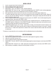
DIAGNOSTICS The bank of temperature indicators indicates that a fault exists. Count the number of flashes between pauses and use this chart as a guide to investigating the fault.
SERVICE This section provides procedures for testing and replacing various major components used in this brewer should service become necessary. Refer to Troubleshooting for assistance in determining the cause of any problem. WARNING - Inspection, testing, and repair of electrical equipment should be performed only by qualified service personnel. The brewer should be unplugged when servicing, except when electrical tests are required and the test procedure specifically states to plug in the brewer.
SERVICE (cont.) C A U T IO N : W A R M E R S A N D S U R F A C E S A R E H O T CONTROL BOARD P1846 FIG. 2 CONTROL BOARD Location: The Control Board is located inside the top cover behind the front end cap. Test Procedures: The test procedures for the control board will vary depending upon the problems experienced by the brewer. Refer to the Troubleshooting guide beginning on page 9.
SERVICE (cont.) SWITCH PANEL P1848 FIG. 3 SWITCH PANEL Location: The Switch Panel is located in the front of the hood. Removal and Replacement: 1. Disconnect the 11-pin connector to the switch panel from the control board. 2. Remove the four #6 screws, nylon washers and the two #4-40 screws securing the control board to the end cap assembly and set aside. 3. Gently pry the switch panel from the end cap assembly. 4 Remove any adhesive that remains on the end cap. 5.
SERVICE (cont.) DISPENSE VALVE 6. Connect the voltmeter lead ends to the dispense valve coil terminals. Connect the brewer to the power source. Brewer temperature lockout must be disabled. Place "ON/OFF" Switch in the "ON" position. Press and release the brew switch. The indication must be 120 volts ac for two-wire 120 volt models and three-wire 120/208 volt models. 7. Disconnect the brewer from the power source.
SERVICE (cont.) LIMIT THERMOSTAT Removal and Replacement: 1. Remove the black and blue wires from limit thermostat terminals. 2. Carefully slide the limit thermostat out from under the retaining clip and remove limit thermostat. 3. Carefully slide the new limit thermostat into the retaining clip. 4. Refer to FIG. 7 when reconnecting the wires. BLU from Control Board P1854 FIG.
SERVICE (cont.) TANK HEATER If continuity is present as described, reconnect the wires, the tank heater is operating properly. If continuity is not present as described, replace the tank heater. NOTE- If the tank heater remains unable to heat, remove and inspect heater for cracks in the sheath. P1855 FIG. 8 TANK HEATER Location: The tank heater is located inside the tank and secured to the tank bottom. Test Procedures: 1. Disconnect the brewer from the power supply. 2.
SERVICE (cont.) TANK HEATER (Cont.) 18. Install tank lid and secure in place with eight #8-32 nuts. 19. Connect the two white wires of the tank warmer blanket. 20. Connect the limit thermostat to the front of the tank assembly. 21. Connect the green wire to the tank mounting bracket using #8-32 nut. 22. Connect the pink wire to the level probe. 23. Insert the temperature probe through the grommet in the tank lid. 24. Install the elbow fitting of the vent hose into the grommet in the tank lid. 25.
SERVICE (cont.) REFILL VALVE If continuity is not present as described, replace the refill valve. 6. Check the refill valve for coil action. Connect the brewer to the power source. With "ON/OFF" switch in the "ON' upper position press start switch and listen carefully in the vicinity of the refill valve for a" clicking" sound as the coil magnet attracts. 7. Disconnect the brewer from the power source.
SERVICE (cont.) WARMER ELEMENT(S) If voltage is present as described, proceed to #5. If voltage is not present as described, refer to Wiring Diagrams and check brewer wiring harness. 5. Check the continuity across the two terminals on the warmer element. If continuity is present as described, reconnect the two wires to the warmer element. If continuity is not present as described, replace the warmer element. P2675 FIG. 12 WARMER ELEMENTS Location: The warmer element(s) is located under the warmer plate.
SCHEMATIC WIRING DIAGRAM CDBC - 15, 20 & 35 L1 LIMIT THERMOSTAT BLU-14 BLK-14 B O A R D J1-10 WHI/BLU WHI/GRN WHI WHI SOL WHI WARMER ASSY "A" BRN/BLK VIO CONTROL PANEL ASSY LT FRNT SW LT REAR SW BREW SW ON/OFF SW TOP FRNT SW TOP REAR SW HIDDEN SW RT REAR SW P2 P3 BRN/BLK FRONT WARMER WHI P1 (SEE TABLE BELOW FOR USAGE) W H I REAR WARMER VIO YEL P2 P3 YEL FRONT WARMER WHI WHI P1, P2, & P3 ARE PINS OF A POLARIZED THREE-PIN CONNECTOR.
SCHEMATIC WIRING DIAGRAM CDBCP/CDBCPF - 15, 20 & 35 N L2 L1 W/Flashing Lamp (Freshness) GRN LIMIT THERMOSTAT BLU-14 BLK-14 BLK-14 TANK HEATER WHI-14 (MODELS 15 & 20) RED-14 (MODEL 35) "KEEP WARM" HEATER WHI WHI BLK BREW STATION WARMER WHI/RED (CONTROLLED BY ON/OFF SW) WHI REFILL C O N T R O L RED TRM-1 BLK TRM-2 BLU-14 COM BLK-14 N.O.
SCHEMATIC WIRING DIAGRAM SINGLE CD - 15, 20 & 35 L1 LIMIT THERMOSTAT BLU-14 BLK-14 WHI COUNTER (OPTIONAL) C B O A R D J1-10 WHI/BLU DISPENSE WHI/GRN BRN/BLK J3-1 J3-4 J5-1 P1 WHI/VIO P3 WHI P1, P2, & P3 ARE PINS OF A POLARIZED THREE-PIN CONNECTOR.
SCHEMATIC WIRING DIAGRAM CDBCP DB/CDBCFP DB L1 L2 GRN MAIN POWER SWITCH LIMIT THERMOSTAT BLU-14 BLK-14 BLK-14 TANK HEATER "KEEP WARM" HEATER WHI BLK WHI/RED WHI BREW STATION WARMER (CONTROLLED BY ON/OFF SW) J1-5 C B O A R D REFILL BLK J1-1 BLK J1-2 BLU-14 COM BLK-14 N.O.
SCHEMATIC WIRING DIAGRAM CDBCP DB/CDBCFP DB L1 L2 GRN MAIN POWER SWITCH LIMIT THERMOSTAT BLU-14 BLK-14 BLK-14 TANK HEATER "KEEP WARM" HEATER WHI BLK WHI/RED WHI BREW STATION WARMER (CONTROLLED BY ON/OFF SW) J1-5 C B O A R D REFILL BLK J1-1 BLK J1-2 BLU-14 COM BLK-14 N.O.