BUNN N ON ATI OR RP CO TIC .A. MA U.S -O- IS, NN BU ILLINO BY TTS ED FIELD, S/N WA RTZ TUR ING HE TS : FAC SPR TEN P PA AM E G WIR WIN LLO FO . A.C THE DE OF LTS G MO RE VO E DIN AS MO PH OR PEN E Y BE R ON MA DE TS UN TEN ED VER R PA HE CO OT RE MO E OR ON N U B MA L NU ® CEZ-APS, CDBC-APS, CEZ-TS, CDBC-TS, CEZ-TSR, CDBC-TSR N ON ATI OR RP CO TIC .A. MA U.S -O- IS, NN BU ILLINO BY TTS ED FIELD, S/N WA RTZ TUR ING HE TS : FAC SPR TEN P PA AM E G WIR WIN LLO FO . A.
INTRODUCTION This equipment will automatically brew a half-gallon batch of coffee into an awaiting server at the press of a button. A hot water faucet may be included for allied beverage use. Most functions of the brewer are digitally controlled. It is only for indoor use on a sturdy counter or shelf. CONTENTS Introduction & Warranty .................................................................................... 2 User Notices ............................................................................
USER NOTICES Carefully read and follow all notices in this manual and on the equipment. All labels on the equipment should be kept in good condition. Replace any unreadable or damaged labels.
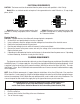
ELECTRICAL REQUIREMENTS CAUTION - The brewer must be disconnected from the power source until specified in Initial Set-Up. Model 15 has an attached cordset and requires 2-wire grounded service rated 120 volts ac, 15 amp, single phase, 60 Hz. L2 RED WHITE NEUTRAL L1 BLACK WHITE 120V.A.C. 120V.A.C. 208 or 240V.A.C. NEUTRAL 120V.A.C. L1 BLACK Model 20 requires 2-wire, grounded service rated 120 volts ac, 20 amp, single phase, 60 Hz.
OPERATING CONTROLS Model CEZ-APS/TS/TSR ON/OFF SWITCH Placing the "ON/OFF" switch in the "ON" upper position enables the brew circuit, and energizes the tank refill circuit. Placing the switch in the "OFF" lower position stops tank refilling and brewing. Stopping a brew cycle after it has been started will not stop the flow of water into the server until the funnel is empty.
INITIAL SET-UP 1. 2. 3. 4. 5. 6. 7. 8. 9. Insert an empty funnel into the funnel rails. Place an empty server under the funnel. Connect the brewer to the power source. Model CDBC-APS/TS/TSR – Press the "ON/OFF" switch (indicator glowing). Model CEZ-APS/TS/TSR – Place the "ON/OFF" switch in the "ON" upper position. Water will flow into the tank and stop when the tank is filled to its capacity. Wait approximately twenty minutes for the water in the tank to heat to the proper temperature.
CEZ-APS/TS/TSR ADJUSTMENTS & OPTIONAL SETTINGS Page 7
CDBC-APS/TS/TSR ADJUSTMENTS & OPTIONAL SETTINGS P1912 Setting Brew Temperature The brewer is factory set to brew at 200°F(95°C). To change this setting, press and hold the "HIDDEN" switch beneath the "®". The word "TEMP" above the "ON/OFF" switch will glow to correspond with the temporary function change of this switch. Repeatedly press and release the "ON/OFF" switch until one of the bank of temperature indicators shows the approximate desired temperature.
TROUBLESHOOTING A troubleshooting guide is provided to suggest probable causes and remedies for the most likely problems encountered. If the problem remains after exhausting the troubleshooting steps, contact the Bunn-O-Matic Technical Service Department. • • • • • • • Inspection, testing, and repair of electrical equipment should be performed only by qualified service personnel. All electronic components have 120 volt ac and low voltage dc potential on their terminals.
TROUBLESHOOTING (cont.) REFILL CIRCUIT PROBLEM PROBABLE CAUSE REMEDY Will not fill or refill 1. Power off to brewer (CDBCAPS/TS/TSR & CEZ-APS/TS/TSR) Press ON/OFF switch on control panel to determine if power is ON. 2. Water shut off (CDBC-APS/TS/ TSR & CEZ-APS/TS/TSR) Make sure water is ON. 3. Display flashing (CDBC-APS/ TS/TSR) or ready light flashing (CEZ-APS/TS/TSR) Brewer has shut down due to malfunction (See Diagnostic Chart in manual, Page 19, or under top lid of brewer). 4.
TROUBLESHOOTING (cont.) REFILL CIRCUIT (cont.) PROBLEM PROBABLE CAUSE REMEDY Fill or refill does not shut "OFF" (ON/OFF Switch "ON") 1. Lime build up on probe (CDBCAPS/TS/TSR & CEZ-APS/TS/TSR) Remove Probe and check for lime deposits on tip. Clean and reinstall. 2a. Water Level Probe Sensing System (CDBC-APS/TS/TSR) A) Disconnect the brewer from the power source. Disconnect the J3 connector from the control board.
TROUBLESHOOTING (cont.) HEATING CIRCUIT PROBLEM PROBABLE CAUSE REMEDY Water does not heat to proper temperature 1. Display flashing (CDBC-APS/ TS/TSR) or ready light flashing (CEZ-APS/TS/TSR) Brewer has shut down due to malfunction (See Diagnostic Chart in manual, Page 19, or under top lid). 2. Water not touching temperature probe Remove probe and grommet. Look into hole on tank lid. Water must be within one inch from top of tank. 3a.
TROUBLESHOOTING (cont.) HEATING CIRCUIT (cont.) PROBLEM PROBABLE CAUSE REMEDY Water does not heat to proper temperature (cont.) 4a. Temperature Probe (CDBCAPS/TS/TSR) A) Remove the probe from the grommet and submerge in a water bath of approximately 70°F(21°C). Connect an ohmmeter to pins 3 and 4 of the J3 connector. At 60°F(16°C) the reading should be 15.3k ± 2k OHMS, at 70°F(21°C) the reading should be 11.8k ± 2k OHMS, and at 80°F(27°C) the reading should be 9.3k ± 2k OHMS.
TROUBLESHOOTING (cont.) HEATING CIRCUIT (cont.) PROBLEM PROBABLE CAUSE REMEDY Spitting or excessive steaming (cont.) 2a. Temperature Probe (CDBCAPS/TS/TSR) A) Remove the probe from the grommet and submerge in a water bath of approximately 70°F(21°C). Connect an ohmmeter to pins 3 and 4 of the J3 connector. At 60°F(16°C) the reading should be 15.3k ± 2k OHMS, at 70°F(21°C) the reading should be 11.8k ± 2k OHMS, and at 80°F(27°C) the reading should be 9.3k ± 2k OHMS.
TROUBLESHOOTING (cont.) BREWING CIRCUIT PROBLEM PROBABLE CAUSE REMEDY Brew cycle will not start 1. Display flashing (CDBC-APS/ TS/TSR) or ready light flashing (CEZ-APS/TS/TSR) Brewer has shut down due to malfunction (See Diagnostic Chart in manual, Page 19, or under top lid of brewer). 2. No water Water lines and valves to the brewer must be open. 3. No power or incorrect voltage to the brewer Check for voltage across the black and white terminals at the terminal block. 4.
TROUBLESHOOTING (cont.) BREWING CIRCUIT (cont.) PROBLEM PROBABLE CAUSE REMEDY Brew cycle will not start (cont.) 8. Control board or dispense valve (CDBC-APS/TS/TSR & CEZ-APS/ TS/TSR) If the start switch (CEZ-APS/TS/ TSR) or switch panel (CDBC-APS/ TS/TSR) is operating properly, proceed as follows. Attach a voltmeter to the terminals of the dispense valve solenoid. Connect the brewer to the power source. Turn on the brewer and press the BREW switch. Voltage should be present at the solenoid terminals.
TROUBLESHOOTING (cont.) BREWING CIRCUIT (cont.) PROBLEM PROBABLE CAUSE REMEDY Dripping from sprayhead 1. Lime build up Inspect the tank assembly for excessive lime deposits. Delime as required. 2. Dispense valve Remove the dispense valve and clear any obstructions. Rebuild or replace the valve if necessary.(See page 26) 1. Sprayhead A six-hole stainless steel sprayhead must be used for proper extraction. 2. Water temperature Place an empty brew funnel on an empty server beneath the sprayhead.
TROUBLESHOOTING (cont.) BREWING CIRCUIT (cont.) PROBLEM PROBABLE CAUSE REMEDY Dry coffee grounds remain in the funnel 1. Sprayhead Make sure sprayhead is present and holes are clear and unobstructed. There should be six separate streams of water coming out of the sprayhead. 2. Funnel loading The BUNN® paper filter must be centered in the funnel and the bed of grounds leveled by shaking gently.
DIAGNOSTICS Intermittent flashing of the READY indicator (Model CEZ) or the bank of temperature indicators (Model CDBC) indicates that a fault exists. Count the number of flashes between pauses and use this chart as a guide to investigating the fault.
SERVICE This section provides procedures for testing and replacing various major components used in this brewer should service become necessary. Refer to Troubleshooting for assistance in determining the cause of any problem. COMPONENT ACCESS N O H E R A S E C A F R U S D N A N S R E M R A W : N T MOR U OR U FOL . A.C THE TS EOF G VOL SE DIN MOR PHAOR PEN BE ONE S MAY ENT PAT ER E OTH IO ER T N ATIO POR COR TIC A. -MA U.S.
SERVICE (cont.) CONTROL BOARD - Model CDBC-APS/TS/TSR N N ATIO POR COR TIC A. -MA U.S. N-ONOIS, BUNILLI BY D, TS WATTZ RED FIEL S/N CTU ING HER S : UFA SPR ENT MAN PAT AMPE ING WIR LOW N U B EL MOD ER D UND ERE COV OR FOL . A.C THE TS EOF G VOL SE DIN MOR PHAOR PEN BE ONE S MAY ENT PAT ER E OTH MOR ONE P1914 FIG. 2 CONTROL BOARD Location: The Control Board is located inside the top cover behind the front end cap. Removal and Replacement: 1.
SERVICE (cont.) CONTROL BOARD - Model CEZ-APS/TS/TSR J1 1 TRM 2 TRM J2 J3 W A R M E R S A N D S U R F A C E S A R J4 E H O T J5 C J7 A U T IO N : J6 P1915 FIG. 3 CONTROL BOARD Location: The Control Board is located inside the trunk behind the front access panel. Test Procedures: The test procedures for the control board will vary depending upon the problems experienced by the brewer. Refer to the Troubleshooting guide beginning on page 9.
SERVICE (cont.) SWITCH PANEL - Model CDBC-APS/TS/TSR N N IO AT OR RP CO IC AT U.S.A. -M -O OIS, NN BU ILLIN BY LD, TS ED WAT Z S/N UR NGFIE RT CT HE S : FA SPRI NT NU TE P MA PA AM E ING IR W OW LL E FO A.C. TH L S DE OF LT MO RE VO E ING AS MO ND PH OR PE E BE Y R ON DE S MA NT D UN TE RE VE R PA HE CO OT B E OR ON U N RE MO P1916 FIG. 4 SWITCH PANEL Location: The Switch Panel is located in the front of the hood. Removal and Replacement: 1.
N N IO AT OR RP N CO IC AT U.S.A. -M -O OIS, NN BU ILLIN , BY ED FIELD S/N U TS WAT Z RT HE S : NT TE P PA AM E ING WIROW LL E FO A.C.
SERVICE (cont.) BREW SWITCH (Start) - Model CEZ-APS/TS/TSR N N A S E C A F R U S D N A S R M R ING A ND Y BE PE W R ON E A.C. TH S OF LT RE VO E AS MO PH OR E L TS WAT Z RT HE S : NT TE P PA AM E ING WIROW LL E FO S MA DE D UN NT R PA TE : RE VE OT T MO U E OR N HE RE IO DE MO O R E RP CO IC A. U.S.
SERVICE (cont.) 6. Connect the voltmeter lead ends to the dispense valve coil terminals. Connect the brewer to the power source. Brewer temperature lockout must be disabled. Place "ON/OFF" Switch in the "ON" position. Press and release the brew switch. The indication must be 120 volts ac for two-wire 120 volt models and three-wire 120/208 volt models. 7. Disconnect the brewer from the power source.
N ON ATI OR RP CO TIC .A. MA U.S -O- IS, NN BU ILLINO BY TTS ED FIELD, S/N WA RTZ TUR ING HE TS : FAC SPR TEN P PA AM E G WIR WIN LLO FO . A.
SERVICE (cont.) If continuity is present as described, reconnect the wires, the tank heater is operating properly. If continuity is not present as described, replace the tank heater. TANK HEATER NOTE- If the tank heater remains unable to heat, remove and inspect heater for cracks in the sheath. P1855 FIG. 13 TANK HEATER Location: The tank heater is located inside the tank and secured to the tank bottom. Test Procedures: 1. Disconnect the brewer from the power supply. 2.
SERVICE (cont.) TANK HEATER (Cont.) 17. Install tank assembly onto mounting brackets and secure in place with four #8-32 nuts. 18. Install tank lid and secure in place with eight #8-32 nuts. 19. Connect the two white wires of the tank warmer blanket. 20. Connect the limit thermostat to the front of the tank assembly. 21. Connect the green wire to the tank mounting bracket using #8-32 nut. 22. Connect the pink wire to the level probe. 23. Insert the temperature probe through the grommet in the tank lid. 24.
J1 TR TR M1 M2 J2 J3 J5 J4 J6 J7 Page 30
SCHEMATIC WIRING DIAGRAM CDBC-APS/TS/TSR L1 N GRN LIMIT THERMOSTAT BLU-14 BLK-14 BLK-14 TANK HEATER WHI-14 (MODELS 15 & 20) RED-14 (MODEL 35) "KEEP WARM" HEATER WHI L2 WHI BLK BLK WHI COUNTER (OPTIONAL) C O N T R O L GRN BLK J1-1 BLK J1-2 BLU-14 COM BLK-14 N.O.
SCHEMATIC WIRING DIAGRAM CEZ-APS/TS/TSR TANK HEATER WHI WHI WHI BREW SWITCH 29341.