TITAN DUAL™ TITAN SINGLE™ SERVICE & REPAIR MANUAL BUNN-O-MATIC CORPORATION POST OFFICE BOX 3227 SPRINGFIELD, ILLINOIS 62708-3227 PHONE: (217) 529-6601 FAX: (217) 529-6644 41747.
BUNN-O-MATIC COMMERCIAL PRODUCT WARRANTY Bunn-O-Matic Corp. (“BUNN”) warrants equipment manufactured by it as follows: 1) Airpots, thermal carafes, decanters, GPR servers, iced tea/coffee dispensers, MCP/MCA pod brewers thermal servers and Thermofresh servers (mechanical and digital)- 1 year parts and 1 year labor. 2) All other equipment - 2 years parts and 1 year labor plus added warranties as specified below: a) Electronic circuit and/or control boards - parts and labor for 3 years.
INTRODUCTION This equipment will brew coffee into an awaiting server or airpot. The brewer may have an auxillary hot water faucet. It is only for indoor use on a sturdy and level counter or shelf. Please install in an area where there are no water jet devices. This brewer can be programmed to adjust different functions of the brewing process, such as brew temperature, brew volumes, bypass percentages, pulse brew, etc. Other features are Energy Savings mode, Freshness Timer and Clean Alert.
TROUBLESHOOTING A troubleshooting guide is provided to suggest probable causes and remedies for the most likely problems encountered. If the problem remains after exhausting the troubleshooting steps, contact the Bunn-O-Matic Technical Service Department. • • • • • • • Inspection, testing, and repair of electrical equipment should be performed only by qualified service personnel. All electronic components have 120-240 volt ac and low voltage dc potential on their terminals.
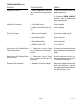
TROUBLESHOOTING (cont.) PROBLEM PROBABLE CAUSE REMEDY Temperature Too Low 1. Water temperature in the tank does not meet the ready temperature. A) Wait for the brewer to heat to the proper temperature. 1. Tank Heater failure. Service required 2. Control Board/Thermistor failure Service required 1. Water shut off to brewer Check water supply shut-off 2. Inlet Solenoid failure Service Required 3. Control Board failure Service Required 4.
TROUBLESHOOTING (cont.) PROBLEM PROBABLE CAUSE REMEDY Brew cycle will not start 1. No water Check plumbing and shut-off valves 2. No power or incorrect voltage to the brewer Check for voltage across the terminals at the terminal block. 3. ON/OFF switch Test the ON/OFF switch. Refer to the test switch procedures on page 17. 4. Brew switch Test the BREW switch. Refer to the test switch procedures on page 17. 5. Brew valve Test the brew valve. Refer to the test outputs procedures on page 15. 6.
TROUBLESHOOTING (cont.) PROBLEM PROBABLE CAUSE REMEDY Automatic refill will not operate or display shows FILL TIME TOO LONG 1. No water Check plumbing and shut-off valves 2. Refill valve Remove the strainer and check for obstructions. Clear or replace. 3. Refill probe or Sensitivity setting Check the sensitivity setting. Refer to the REFILL function in Programmimg Manual.
TROUBLESHOOTING (cont.) PROBLEM PROBABLE CAUSE Automatic refill will not operate or display shows FILL TIME TOO LONG (Continued) REMEDY Refill valve – Disconnect the brewer from the power source and remove wires from refill valve coil. Check for continuity across the terminals of the solenoid coil. If continuity is not present, replace the refill valve. If continuity is present, the coil may be stuck closed. Shut water off to brewer. Press the ON/OFF switch to turn off the brewer.
TROUBLESHOOTING (cont.) PROBLEM PROBABLE CAUSE REMEDY Water flows into tank continuously with power removed from brewer. 1. Refill valve Foreign material lodged in valve, holding it in open state. 2. Refill probe or sensitivity setting Check the sensitivity setting. Refer to the REFILL function in Programming Manual. If the left three digit number is less than the right number, the machine “thinks” it is full and the refill valve should be off.
TROUBLESHOOTING (cont.) PROBLEM PROBABLE CAUSE REMEDY Water will not heat or display shows HEATING TIME TOO LONG. 1. Limit Thermostats Remove power from the brewer. Check for continuity through the limit thermostat. CAUTION: Do not eliminate or bypass limit thermostat. Use only replacement part 23717.0003. 2. Temperature probe Remove the probe from the grommet and submerge in a water bath of approximately 70°F (21°C). Connect an ohmmeter to the pins in the connector.
TROUBLESHOOTING (cont.) PROBLEM PROBABLE CAUSE REMEDY No bypass water 1. Bypass valve Test the bypass valve. Refer to the test outputs procedures on page 15. Spitting or unusual steaming from sprayhead or air vent. 1. Lime buildup Inspect the probe and tank assembly for excessive lime deposits. Delime as required. 2. Temperature probe Remove the probe from the grommet and submerge in a water bath of approximately 70°F (21°C). Connect an ohmmeter to the pins in the connector.
TROUBLESHOOTING (cont.) PROBLEM PROBABLE CAUSE REMEDY Inconsistent beverage level in server/dispenser 1. Improper water pressure Check operating water pressure to the brewer. It must be between 20 and 90 psi (138 and 620 kPa). 2. Brew valve Test the brew valve. Refer to test outputs on page 15. Turn the valve on for 30 seconds and collect the water dispensed from the sprayhead. Repeat the test several times to confirm a consistent volume of dispensed water.
TROUBLESHOOTING (cont.) PROBLEM PROBABLE CAUSE REMEDY Dripping from sprayhead. 1. Brew valve Repair or replace leaky valve Water overflows filter. 1. Type of paper filter BUNN paper filters should be used for proper extraction 2. No sprayhead Check sprayhead 1. Beverage left in server from previous brew The brew cycle should be started only with an empty server under the funnel. 2.
TROUBLESHOOTING (cont.) PROBLEM PROBABLE CAUSE REMEDY Weak beverage. 1. Type of paper filter BUNN paper filters should be used for proper extraction 2. Coffee A sufficient quantity of fresh drip or regular grind should be used for proper extraction. 3. Sprayhead Bunn-O-Matic sprayhead should be used to properly wet the bed of ground coffee in the funnel 4. Funnel Loading The BUNN paper filter should be centered in the funnel and the bed of grounds leveled by gently shaking.
TROUBLESHOOTING (cont.) SERVICE TOOLS This function allows the testing of individual components and the ability to check switches for proper function.
TROUBLESHOOTING (cont.) SERVICE TOOLS (cont.
TROUBLESHOOTING (cont.) SERVICE TOOLS (cont.) Procedure to test switches: This function allows the operator to test the operation of the individual switches on the front panel. The following switches can be individually tested: NOTE: If the operator wishes to test more than one function in the SERVICE TOOLS section (outputs or switches), it is not necessary to exit the program. Use the flow chart for SERVICE TOOLS to navigate to a particular function.
CONPONENT ACCESS This section provides procedures for testing and replacing various major components used in this brewer should service become necessary. Refer to Troubleshooting for assistance in determining the cause of any problem. WARNING - Inspection, testing, and repair of electrical equipment should be performed only by qualified service personnel.
CONPONENT ACCESS (cont) 4. Remove the adhesive backing from the new membrane switch. Insert the ribbon cable through the slot in the hood and apply the membrane switch to the front of the hood. 5. Reconnect the ribbon cable to the 22-pin connector on the control board making sure every pin on the control board is inserted into the ribbon cable connector.
CONPONENT ACCESS (cont) BYPASS VALVES Dispense Valve If voltage is present as described, but no coil action is observed, valve is defective. Replace valve and test again to verify repair. If voltage is not present as described, refer to Wiring Diagrams and check the brewer wiring harness. Also check the control board and switch for proper operation. Contactor Bypass Valve FIG 3 BYPASS/DISPENSE VALVES Location: The bypass valve(s) (Fig 3) are located inside the hood under the top cover.
CONPONENT ACCESS (cont) DISPENSE VALVES (cont) 4. Connect the voltmeter leads to the coil terminals. Set the meter to AC volts. Turn on the valve with the test mode. The indication should be the line voltage rated for that model. If voltage is present as described, but no coil action is observed, valve is defective. Replace valve and test again to verify repair. If voltage is not present as described, refer to Wiring Diagrams and check the brewer wiring harness.
CONPONENT ACCESS (cont) REFILL VALVE (cont) 4. Remove the two 1/4"-20 screws securing the valve to the component mounting bracket. 5. Using the two 1/4"-20 screws, install the new valve to the component mounting bracket. 6. Securely fasten the water lines to the valve. 7. Refer to wiring diagrams when reconnecting the wires. 8. Install access panels and covers and refer to Initial Set-up for refill and operation. TANK HEATERS 3. Disconnect the wires from the tank heater terminals. 4.
CONPONENT ACCESS (cont) If resistance is not to specification, replace the temperature probe. LIMIT THERMOSTATS (cont) If continuity is present as described, the limit thermostat is operating properly. If continuity is not present as described, replace the limit thermostat. Removal and Replacement: 1. Remove the wires from limit thermostat terminals. 2 Remove the two #8-32 nuts securing the limit thermostat to the tank lid and lift limit thermostat off the studs. 3.
CONPONENT ACCESS (cont) POWER SWITCH CONTACTOR (cont) Diagrams and check the brewer wiring harness. 5. Locate the black, red and blue wires on the L1, L2 and L3 terminals on the contactor. 6. With a voltmeter, carefully check the voltage across L1-L2, L1-L3 and L2-L3. The indication must be, 208 volts ac for 120/208 volt models, 240 volts ac for 120/240 volt models or 230 volts ac for 230/400 volt models. 7. Disconnect the brewer from the power source.
SCHEMATIC WIRING DIAGRAM TITAN SINGLE BLU L3 RED L2 L1 BLK TERMINAL BLOCK MAIN ON/OFF SWITCH E SE BLK BLK RED RED BLU BLU J20-3 COM N.O. J17-1 LIMIT #3 BLK RED SOL BLU TANK HEATER #2 TANK HEATER #3 BLU BLK RED RED/BLK BLK BYPASS HEATER #2 LIMIT #1 LIMIT #2 LIMIT #3 T LIMIT #3 BLU BLK RED WHI DISPENSE WHI/RED WHI SOL WHI/GRN J17-5 RED TANK HEATER #1 HEATER #3 WHI 2.
SCHEMATIC WIRING DIAGRAM TITAN SINGLE CE N WHI-12 BLU-12 L3 L3 BLU-12 RED-12 L2 L2 RED-12 BLK-12 L1 L1 BLK-12 N EMI FILTER L2 L1 E SE BLK-12 BLK-12 RED-12 RED-12 BLU-12 BLU-12 BLK TERMINAL BLOCK J17-1 LIMIT #1 LIMIT #2 LIMIT #3 LIMIT #3 RED-12 BLU-12 TANK HEATER #1 TANK HEATER #2 TANK HEATER #3 VIO-12 VIO-12 VIO-12 BLK LIMIT #1 LIMIT #2 LIMIT #3 WHI WHI WHI WHI 2.
L2 L3 SCHEMATIC WIRING DIAGRAM TITAN SINGLE N GRN WHI • FOR 3 PHASE OPERATION, WIRE AS SHOWN. BLU L3 • FOR SINGLE PHASE OPERATION, MOVE BLU WIRE INTO CELL WITH BLK WIRE; APPLY POWER ACROSS L1, L2 AND N. RED L2 BLU RED BLK BLK TERMINAL BLOCK BLK TERMINAL BLOCK MAIN ON/OFF SWITCH BLK BLK L1 L1 BLK J17-1 RED SOL RED/BLK BLK SWEETENER INJECTOR LIMIT #1 RED WHI DISPENSE WHI/RED WHI SOL WHI/GRN J17-5 BLU WHI 2.2uF J21-1 COM N.O.
L1 L2 L3 SCHEMATIC WIRING DIAGRAM TITAN DUAL 200V GRN LIMIT #2 LIMIT #1 HEATER #2 HEATER #3 LIMIT #3 WHI-12 MAIN ON/OFF SWITCH N N BLU-12 L3 L3 BLU-12 RED-12 L2 L2 RED-12 BLK-12 L1 L3 L2 BLK-12 L1 EMI FILTER BLK-12 L1 BLK TERMINAL BLOCK T1 L1 RED-12 J20-3 J17-5 J17-10 J17-14 LIMIT #2 3 4 LIMIT #3 BLU-12 BLK T3 BLK-12 RED-12 TANK HEATER #1 TANK HEATER #2 VIO-12 SOL RED/BLK BLK RED 2 BLU-12 TANK HEATER #3 2 LEFT BYPASS 1 WHI WHI LEFT DISPENSE SOL BLK GR
L1 L2 L3 N SCHEMATIC WIRING DIAGRAM TITAN DUAL CE GRN WHI-12 BLU-12 BLK-12 RED-12 TERMINAL BLOCK MAIN ON/OFF SWITCH • FOR 3 PHASE OPERATION, WIRE AS SHOWN.
L1 L2 L3 N SCHEMATIC WIRING DIAGRAM TITAN DUAL GRN WHI-12 • FOR 3 PHASE OPERATION, WIRE AS SHOWN.