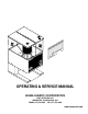
OPERATING & SERVICE MANUAL BUNN-O-MATIC CORPORATION POST OFFICE BOX 3227 SPRINGFIELD, ILLINOIS 62708-3227 PHONE: (217) 529-6601 FAX: (217) 529-6644 www.bunnomatic.
CONTENTS User Notices .............................................................3 Electrical Requirements ............................................3 Operating Controls....................................................3 Cleaning ....................................................................4 Coffee Grinding .........................................................4 Initial Set-Up .............................................................5 Adjustments .........................................
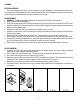
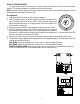
CLEANING EXTERIOR SURFACES The use of a damp cloth rinsed in any mild, nonabrasive, liquid detergent is recommended for cleaning all surfaces on Bunn-O-Matic equipment. Care should be taken not to scratch the hopper or windows with any abrasive material. Regular cleaning will keep your grinder looking new for years. GRIND CHAMBER 1. WARNING - Unplug grinder before removal of any panel or grind chamber housing parts. 2. Empty all beans from both hopper(s). 3.
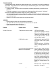
INITIAL SET-UP/ADJUSTMENTS The grind can be set from fine to very coarse. The grind may be adjusted for use in most commercial coffee brewers. The following procedures should be used to make adjustments. NOTE - A change in the burr adjustment will also change the amount dispensed. Any adjustment to the burrs should be followed by an adjustment of the timer dials. SE - F INE AR Burr Adjustment CO 1. Unplug the grinder and empty all beans from the hopper(s). 2.
TROUBLESHOOTING A troubleshooting guide is provided to suggest probable causes and remedies for the most likely problems encountered. If the problem remains after exhausting the troubleshooting steps, contact the Bunn-O-Matic Technical Service Department. • Inspection, testing, and repair of electrical equipment should be performed only by qualified service personnel. • All electronic components have ac voltage and dc voltage potential on their terminals.
TROUBLESHOOTING (cont.
SERVICE This section provides procedures for testing and replacing various major components used in this grinder should service become necessary. Refer to Troubleshooting for assistance in determining the cause of any problem. WARNING - Inspection, testing, and repair of electrical equipment should be performed only by qualified service personnel. The grinder should be unplugged when servicing, except when electrical tests are required and the test procedure specifically states to plug-in the grinder.
SERVICE (cont.) Capacitor (Model LPG)(cont.) Location: The capacitor is located inside the front panel of the hopper housing next to the Off/On/Start switch. Test Procedure: 1. Disconnect grinder from the power source. 2. Visually inspect the capacitor for leakage. If leakage is visible, replace the capacitor. 3. Connect the grinder to the power source, if the motor does not run, disconnect the capacitor wiring harness from the main wiring harness. If the motor now runs, replace the capacitor.
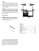
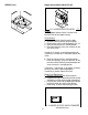
SERVICE (cont.) Hopper Selector Switch (Model LPG-2E) P1029 FIG. 9 HOPPER SELECTOR SWITCH Location: The Hopper Selector Switch is located in the lower left front of the hopper housing. Test Procedure: 1. Disconnect grinder from the power supply. 2. Remove all wires from the switch terminals. 3. Check that the switch is installed properly, FIG. 10. 4. Place the selector switch in the left position. 5. Check for continuity across the terminals on the rear of the switch.
SERVICE (cont.) NOTE: Clean all grind burrs and mounting surfaces before reassembly. Motor Removal and Replacement: 1. On Model LPG-2E, disconnect the black wire and the white wire to the motor from the main wiring harness, the red wire to the circuit breaker and the red wire to the Off/On/Start switch. On Model LPG disconnect the motor wiring harness from the main wiring harness. 2.
SERVICE (cont.) 1 Motor (cont.) 9. Slide spacer plate (4) off of burr housing divider (8) and set aside for reassembly. 10. Loosen the #10-32 setscrew (5) securing the mounting ring and solenoid bracket (6) to the burr housing. 11. Lift mounting ring, solenoid bracket and solenoids (6) over the motor and burr housing assembly (9) and set aside for reassembly. 12. Remove the #8-32 setscrew (7) and set aside for reassembly. 13. Lay motor on it’s side. 2 3 4 6 3 NOTE: Refer to Fig.
SERVICE (cont.) Motor (cont.) 13 MODEL LPG ONLY 10 11 12 13 14 15 16 17 18 FIG. 14 ROTOR/AUGER, BURRS AND MOTOR COVER 22. Remove the two #8-32 flat head screws securing the motor cover (18) to the motor and housing assembly (17) and remove the cover. Set aside for reassembly. 23. Discard old motor and housing assembly. 24. Place new motor on it’s side and install motor cover (18) using two #8-32 flat head screws. 25.
1. Remove all wires from the switch terminals. 2. Compress the clips inside the front of the hopper housing and gently push the switch through the opening. 3. Push the new switch into the opening and spread the clips to retain the switch in the hopper housing. 4. Reconnect all the wires to the switch terminals. 5. Refer to Fig. 16 when reconnecting the wires. SERVICE (cont.
SERVICE (cont.) Solenoid (cont.) solenoid with a voltmeter. Connect the grinder to the power source and place the Off/On/Start switch in the “ON” center position. The indication must be 120 volts AC. 4. Disconnect the grinder from the power source. If voltage is present as described, proceed to #5. If voltage is not present as described, refer to the wiring diagram and check grinder wiring harness. 5. Check for continuity across the solenoid coil terminals.
SERVICE (cont.) 7. Place the hopper selector switch in the right position. 8. Insert the leads of a voltmeter set to read at least 120 volts AC, along side the red wire (terminal 8) and the violet wire (terminal 9) of the harness plug. Place the Off/On/Start switch in the “START” lower position. Connect the grinder to the power source. The indication must be 120 volts AC for the set gate time and return to 0 volts. 9. Disconnect the grinder from the power source.
SERVICE (cont.) Timer (Model LPG-2E) 3. Disconnect the grinder from the power source. 8. Slip timer and timer mounting bracket under the two screws on the motor support plate and tighten screws. 9. Locate the left and right timer dials in their proper place on the rear panel and secure with nuts and internal tooth lockwashers. 10. Place timer knobs on timers. 11. Reconnect harness plug to the terminal block on the timer board. If voltage is present as described, proceed to step #4.
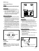
WIRING SCHEMATICS SCHEMATIC WIRING DIAGRAM LPG2E L1 N GRN BLK SELECTOR SWITCH 3 AMP WHI GRN TIMER ASSY. (Hopper Slide Gate Timer Dial Wiring) Right - Brown Left - Orange 1 2 3 4 5 6 7 8 9 10 OFF/ON/START SWITCH WHI BLU YEL WHI/BLK BLK RED VIO ORA BLK GRINDER WHI M RED RED RED RT SOL SLIDE GATES RED RED RED LT SOL RED RED YEL WHI 120 VOLTS AC 2 WIRE SINGLE PHASE 60 HZ 27103.
SCHEMATIC WIRING DIAGRAM LPG & LPG2 L1 N B L K GREEN 3 AMP TIMER RED WHI/BLK BLK WHI/BLU WHI/BRN WHI GRN BLK RED WHI/BRN WHI/BLU DC MOTOR W H I BLK BLK WHI RED RED 120 VOLTS AC 2 WIRE SINGLE PHASE 60 HZ P1 1 2 3 4 5 6 P2 1 2 3 4 5 P3 1 2 3 4 RED WHI/BLK BLK WHI/BLU WHI/BRN WHI BLK RED WHI/BRN WHI/BLU BLK WHI RED RED 10529.
WIRING SCHEMATICS SCHEMATIC WIRING DIAGRAM LPG-A L1 L2 B L K GRN/YEL 3 AMP TIMER RED WHI/BLK BLK WHI/BLU WHI/BRN WHI GRN BLK RED WHI/BRN WHI/BLU DC MOTOR R E D BLK BLK WHI RED RED 230 VOLTS AC 2 WIRE SINGLE PHASE 50/60 HZ P1 1 2 3 4 5 6 P2 1 2 3 4 5 P3 1 2 3 4 RED WHI/BLK BLK WHI/BLU WHI/BRN WHI BLK RED WHI/BRN WHI/BLU BLK WHI RED RED 10529.
SCHEMATIC WIRING DIAGRAM LPG W/Capacitor L1 N GREEN BLK TIMER W H I BLK RED WHI/BLK BLK WHI/BLU WHI/BRN WHI GRN BLK BLK + WHI/BRN _ BLK RED WHI/BRN WHI/BLU DC MOTOR BLK WHI RED RED P1 1 2 3 4 5 6 RED WHI/BLK BLK WHI/BLU WHI/BRN WHI P4 2 1 BLK WHI/BRN P2 1 2 3 4 5 P3 1 2 3 4 BLK RED WHI/BRN WHI/BLU BLK WHI RED RED 10529.
WIRING SCHEMATICS SCHEMATIC WIRING DIAGRAM LPG-B L1 N B L K GREEN 3 AMP TIMER RED WHI/BLK BLK WHI/BLU WHI/BRN WHI GRN BLK RED WHI/BRN WHI/BLU DC MOTOR W H I BLK BLK WHI RED RED 100 VOLTS AC 2 WIRE SINGLE PHASE P1 1 2 3 4 5 6 P2 1 2 3 4 5 P3 1 2 3 4 RED WHI/BLK BLK WHI/BLU WHI/BRN WHI BLK RED WHI/BRN WHI/BLU BLK WHI RED RED 10529.