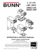
C, CT, CTF, CWT, CWTF, SINGLE CW, SINGLE CWF ON UTI CA C A U T IO N : ! OPERATING & SERVICE MANUAL BUNN-O-MATIC CORPORATION POST OFFICE BOX 3227 SPRINGFIELD, ILLINOIS 62708-3227 PHONE: (217) 529-6601 FAX: (217) 529-6644 To ensure you have the latest revision of the Operating Manual, or to view the Illustrated Parts Catalog, Programming Manual, or Service Manual, please visit the Bunn-O-Matic website, at www.bunn.com.
BUNN-O-MATIC COMMERCIAL PRODUCT WARRANTY Bunn-O-Matic Corp. (“BUNN”) warrants equipment manufactured by it as follows: 1) All equipment other than as specified below: 2 years parts and 1 year labor. 2) Electronic circuit and/or control boards: parts and labor for 3 years. 3) Compressors on refrigeration equipment: 5 years parts and 1 year labor.
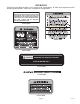
USER NOTICES Carefully read and follow all notices in this manual and on the equipment. All labels on the equipment should be kept in good condition. Replace any unreadable or damaged labels. This equipment must be installed to comply with the International Plumbing Code of the International Code Council and the Food Code Manual of the Food and Drug Administration (FDA). For models installed outside the U.S.A., comply with the applicable Plumbing /Sanitation Code. #00656.0000 #00831.0000 #00658.
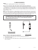
ELECTRICAL REQUIREMENTS WARNING - If the power cord is ever damaged, it must be replaced by the manufacturer or its service agent with a special cord available from the manufacturer or its service agent in order to avoid a hazard. Refer to Data Plate on the Brewer, and local/national electrical codes to determine circuit requirements. Model 15 has an attached cordset and requires 2-wire grounded service rated 120 volts ac, 15 amp, single phase, 60 Hz.
PLUMBING REQUIREMENTS Model C: This model is completely portable and requires no attached plumbing. Models CT, CTF, CWT, CWTA, CWTB, CWTF, CWTFA & CWTFB, SINGLE CW & SINGLE CWF These brewers must be connected to a cold water system with operating pressure between 20 and 90 psi (138 to 620kPa) from a 1⁄2" or larger supply line. A shut-off valve should be installed in the line before the brewer. Install a regulator in the line when pressure is greater than 90 psi (620kPa)to reduce it to 50 psi (345kPa).
INITIAL SET-UP CAUTION - The brewer must be disconnected from the power source throughout the initial set-up, except when specified in the instructions. 1. 2. 3. Insert an empty funnel into the funnel rails. Place an empty dispenser under the funnel. Place the heater switch at the rear of the brewer in the “OFF” lower position and connect the brewer to the power source. 4. Fill the tank with water as directed: 4A. Model C Pour three pitchers of tap water into the screened area on top of the brewer.
tion on the circuit board. To increase a batch size. Press and hold the START or BREW switch until three clicks are heard. Release the switch (Failure to release the switch within two seconds after the third click causes the volume setting to be aborted and previous volume setting will remain in memory) and press it again one or more times. Each time the switch is pressed, two seconds are added to the brew time period.
TROUBLESHOOTING A troubleshooting guide is provided to suggest probable causes and remedies for the most likely problems encountered. If the problem remains after exhausting the troubleshooting steps, contact the Bunn-O-Matic Technical Service Department. • • • • • • • Inspection, testing, and repair of electrical equipment should be performed only by qualified service personnel. All electronic components have 120 volt ac and low voltage dc potential on their terminals.
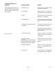
TROUBLESHOOTING (cont.) PROBLEM PROBABLE CAUSE REMEDY Brew cycle will not start (cont.) (CT, CTF, CWT, CWTA, CWTB, CWTF, CWTFA, CWTFB, SINGLE CW & SINGLE CWF) 3. ON/OFF Switch Refer to Service - ON/OFF Switch for testing. See page 17 4. Start Switch Refer to Service - Start Switch for testing procedures. See page 20 5. Timer Refer to Service - Timer for testing procedures. See page 24 6. Solenoid Valve Refer to Service - Solenoid Valve for testing procedures. See page 19 7.
TROUBLESHOOTING (cont.) PROBLEM PROBABLE CAUSE REMEDY Inconsistent beverage level in dispenser 1. Strainer/flow control (.222 GPM) (CT,CTF, CWT, CWTA, CWTB, CWTF, CWTFA, CWTFB, SINGLE CW & SINGLE CWF) (A) Direction of flow arrow must be pointing towards the brewer. 2. Syphon System The brewer must be level or slightly lower in front to syphon properly. 3. Lime Build-up CAUTION - Tank and tank components should be delimed regularly depending on local water conditions.
TROUBLESHOOTING (cont.) PROBLEM PROBABLE CAUSE REMEDY Spitting or excessive steaming (cont.) 2. Control Thermostat Refer to Service - Control Thermostat for testing procedures. See page 15 Dripping from sprayhead 1. Syphon System The brewer must be level or slightly lower in front to syphon properly. 2. Lime Build-up CAUTION - Tank and tank components should be delimed regularly depending on local water conditions.
TROUBLESHOOTING (cont.) PROBLEM PROBABLE CAUSE REMEDY Weak beverage 1. Filter Type BUNN® paper filters must be used for proper extraction. 2. Coffee Grind A fine or drip grind must be used for proper extraction. 3. Sprayhead A clean spray-head must be used for proper extraction. 4. Funnel Loading The BUNN® paper filter must be centered in the funnel and the bed of ground leveled by gentle shaking. 5. Water Temperature Place an empty funnel on an empty dispenser beneath the sprayhead.
TROUBLESHOOTING (cont.) PROBLEM PROBABLE CAUSE REMEDY Brewer is making unusal noises (cont.)(CT, CTF, CWT, CWTA, CWTB, CWTF, CWTFA, CWTFB, SINGLE CW & SINGLE CWF) 4. Tank Heater Remove and clean lime off the tank heater. See page 21 Brewer is making unusal noises (C) 1. Tank Heater Remove and clean lime off the tank heater. See page 21 Low beverage serving temperature 1. Warmer Refer to Service - Warmer element for testing procedures.
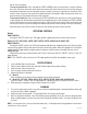
SERVICE PO UR IN W AT ER O NL Y This section provides procedures for testing and replacing various major components used in this brewer should service become necessary. Refer to Troubleshooting for assistance in determining the cause of any problem. WARNING - Inspection, testing, and repair of electrical equipment should be performed only by qualified service personnel.
SERVICE (cont.) 3. CONTROL THERMOSTAT 4. Check the voltage across the blue wire on the control thermostat and the white insert on two pole 120 volt terminal block or three pole 120/240 volt terminal blocks and the red insert on two wire 200 volt or 240 volt terminal block with a voltmeter. Connect the brewer to the power source. The indication must be: a) 120 volts ac for two wire 120 volt models and three wire 120/240 volt models. b) 200 to 230 volts ac for two wire 200 volt or 230 volt models.
LIMIT THERMOSTAT SERVICE (cont.) CONTROL THERMOSTAT (cont.) 4. 5. 6. Slide the grommet to the line 4.5" above the bulb on the new capillary tube. Insert the capillary bulb through the hole in the tank lid and press the grommet firmly and evenly so that the groove in the grommet fits into the tank lid. Carefully bend the capillary tube so that the tube and bulb inside the tank are in the vertical position. NOTE - The capillary tube must be clear of any electrical termination and not kinked. 7. 8. 9.
SERVICE (cont.
SERVICE (cont.) ON/OFF SWITCH (cont.) Test Procedure: 1. Disconnect the brewer from the power source. 2. Viewing the switch from the back remove the white or red wire from the upper terminal and the black wire from the center terminal. 3. Check the voltage across the white wire or red wire and the black wire with a voltmeter. Connect the brewer to the power source. The indication must be: a) 120 volts ac for two wire 120 volt models and three wire 120/240 volt models.
SERVICE (cont.) If continuity is not present as described, replace the solenoid valve. SOLENOID VALVE - CT, CWT & SINGLE CW 6. 7. Check the solenoid valve for coil action. Connect the brewer to the power source. With "ON/OFF" switch in the "ON' upper position press start switch and listen carefully in the vicinity of the solenoid valve for a" clicking" sound as the coil magnet attracts. Disconnect the brewer from the power source.
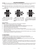
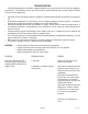
START SWITCH - CT, CWT & SINGLE CW SERVICE (cont.) SELECTOR SWITCH - SINGLE CW only P1153 FIG. 13 START SELECTOR SWITCH LOCATION Location: The start switch is located in the center front of the hood. P1153 FIG. 11 BATCH SELECTOR SWITCH LOCATION Location: The batch selector switch is located on the front of the hood to the right of the start switch. Test Procedure: 1. Disconnect the brewer from the power supply. 2. Disconnect the pink and tan wires from the switch terminals. 3.
SERVICE (cont.) 5. TANK HEATER Check for continuity across the tank heater terminals. If continuity is present as described, reconnect the wires, the tank heater is operating properly. If continuity is not present as described, replace the tank heater. NOTE- If the tank heater remains unable to heat, remove and inspect heater for cracks in the sheath. FIG. 15 TANK HEATER LOCATION P1153 Location: The tank heater is located inside the tank and secured to the tank lid. Test Procedures: 1.
TANK HEATER SWITCH SERVICE (cont.) TANK HEATER (Cont.) 14. Install sprayhead. 15. Reconnect the wires to the limit thermostat, tank heater and control thermostat. See limit thermostat and control thermostat sections in this manual when reconnecting wires. 16. Install fill basin, secure with tank inlet fitting and gasket. Insert water supply line through grommet in fill basin. 17. Refer to the illustration below when reconnecting the tank heater wires.
SERVICE (cont.) TANK HEATER SWITCH (cont.) 5. Check for continuity between the black wire removed from the limit thermostat and the black insert on the terminal block. with the tank heater switch in the "ON" upper position. Continuity should not be present in the "OFF" lower position. If continuity is present as described, the tank heater switch is operating properly. If continuity is not present as described, replace the tank heater switch. Removal and Replacement: 1.
SERVICE (cont.) DIAL TIMER (Early Models) - CT & CWT 6. 7. with a voltmeter when the "ON/OFF" switch is in the "ON" position (upper) and start switch pressed. Connect the brewer to the power source. The indication must be: a) 120 volts ac for two wire 120 volt models and three wire 120/240 volt models. b) 200 to 230 volts ac for two wire 200 volt or 230 volt models. Disconnect the brewer from the power source. Reconnect the three pin connector from main wiring harness to the timer.
SERVICE (cont.) DIAL TIMER (Early Models) (cont.) 2. Remove the #8-32 screw securing circuit board to the mounting bracket. 3. Remove circuit board and spacers (as required). 4. With a voltmeter, check the voltage across terminals TL1 and TL2 when the "ON/OFF" switch is in the "ON" position. Connect the brewer to the power source. The indication must be: a) 120 volts ac for two wire 120 volt models and three wire 120/240 volt models. b) 200 to 230 volts ac on two wire 200 volt or 230 volt models. 5.
SERVICE (cont.) DIGITAL BREW TIMER (Late Models)(cont.) 4. Attach all wires to the replacement timer board prior to installation to the component mounting bracket. Refer to FIG. 22 when reconnecting the wires. 5. Install new circuit board with spacers (as required) to the component mounting bracket. 6. Adjust the timer as described below.
SERVICE (cont.) WARMER ELEMENT(S) If continuity is present as described, reconnect the white or red and white/red, and brown/black or violet wires on the warmer element. If continuity is not present as described, replace the warmer element. Removal and Replacement: 1. Remove the three #4-40 screws securing the warmer assembly to the brewer. 2. Lift the warmer assembly from the brewer. 3. Disconnect the two wires from the warmer element terminals. 4.
SCHEMATIC WIRING DIAGRAM C, CT & CWT L1 BLU HEATER SWITCH BLK LIMIT THERMOSTAT READY BLK SW. & THERMOSTAT BLK BLU BLK N GRN (FAUCET OPTION ONLY) THERMAL FUSE BLK WHI (MODELS 15 & 20) TANK HEATER RED (MODEL 35) WHI WHI ON/OFF SWITCH L2 "KEEP WARM" HEATER WHI 3 BLK 2 1 WHI/RED WHI/RED WHI WHI/ORA L.E.D.
SCHEMATIC WIRING DIAGRAM CWTB L1 BLU HEATER SWITCH BLK LIMIT THERMOSTAT BLK READY BLK SW. & THERMOSTAT (FAUCET OPTION ONLY) THERMAL FUSE BLK BLU L2 GRN/YEL BLK TANK HEATER RED ON/OFF SWITCH RED 3 BLK 2 1 WHI/RED WHI/RED RED LOWER WARMER OPTIONAL AUTOMATIC BREW CIRCUIT START SWITCH BLU WHI/RED P1 BLU/BLK P3 WHI/RED BLK P1, P2, & P3 ARE PINS OF A POLARIZED THREE-PIN CONNECTOR.
SCHEMATIC WIRING DIAGRAM CWTA L1 BLU HEATER SWITCH BLK LIMIT THERMOSTAT BLK SW. & THERMOSTAT L2 GRN/YEL (FAUCET OPTION ONLY) THERMAL FUSE BLK BLU BLK ON/OFF SWITCH READY TANK HEATER BLK RED WHI WHI "KEEP WARM" RED 3 BLK 2 1 WHI/RED WHI/RED RED LOWER WARMER OPTIONAL AUTOMATIC BREW CIRCUIT START SWITCH BLU WHI/RED P1 P3 WHI/RED SOL BLU/BLK BLK P1, P2, & P3 ARE PINS OF A POLARIZED THREE-PIN CONNECTOR.
SCHEMATIC WIRING DIAGRAM CWTF, CWTFB NO WARMER L1 READY INDICATOR BLU HEATER SWITCH BLK BLK LIMIT THERMOSTAT BLK SW. & THERMOSTAT BLU BLK N GRN (FAUCET OPTION ONLY) THERMAL FUSE TANK HEATER BLK WHI (MODELS 15 & 20) RED (MODEL 35) WHI WHI ON/OFF SWITCH L2 "KEEP WARM" HEATER WHI WHI/RED BLK WHI/ORA OPTIONAL AUTOMATIC BREW CIRCUIT START SWITCH OPTIONAL FRESH LIGHT SYSTEM GRY L.E.D.
SCHEMATIC WIRING DIAGRAM CWTFA NO WARMER L1 READY INDICATOR BLU BLK LIMIT THERMOSTAT BLK BLU HEATER SWITCH L2 GRN THERMAL FUSE BLK BLK SW. & THERMOSTAT THERMAL FUSE RED RED TANK HEATER BLK RED BLK WHI WHI ON/OFF SWITCH BLK "KEEP WARM" HEATER RED WHI/RED WHI/ORA OPTIONAL AUTOMATIC BREW CIRCUIT START SWITCH OPTIONAL FRESH LIGHT SYSTEM GRY 4 L.E.D. WHI/RED INDICATOR 3 2 TIMER PNK P3 WHI/RED 1 BLK BLU P1 BLU BLK BLK P1, P2, & P3 ARE PINS OF A POLARIZED THREE-PIN CONNECTOR.