D B ISC ! E R FO ON W E R N P A LA E EC R C RE T E M F N M O R IN E V O N A M G T L P O F OF OW A A E N N R Y Y S C P O O A U M N R P E C O L E N O E R N T! H5E H5X G IN RN ter WAt Wa e! r o a H ry h C Ve Wit e Us ! OPERATING & SERVICE MANUAL BUNN-O-MATIC CORPORATION POST OFFICE BOX 3227 SPRINGFIELD, ILLINOIS 62708-3227 PHONE: (217) 529-6601 FAX: (217) 529-6644 10420.0000K 06/05 © 1989 BUNN-O-MATIC CORPORATION www.bunnomatic.
CONTENTS Introduction ................................................. 2 Warranty ...................................................... 2 User Notices ................................................ 3 Electrical Requirements ............................... 4 Plumbing Requirements .............................. 4 Initial Set-Up ................................................ 5 Draining the Dispenser ................................ 5 Cleaning .......................................................
USER NOTICES The notices on this dispenser should be kept in good condition. Replace unreadable or damaged labels. 12593.0000 00831.0000 00656.0000 10044.
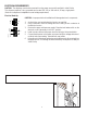
ELECTRICAL REQUIREMENTS CAUTION - The dispenser must be disconnected from the power source until specified in Initial Set-Up. This dispenser requires 2-wire, grounded service rated 120, 208, or 240 volts ac, 20 amp, single phase. (Refer to the dispenser’s dataplate for exact voltage requirement.) Electrical Hook-Up CAUTION – Improper electrical installation will damage electronic components. WHITE NEUTRAL L1 BLACK 120V.A.C. 1. 2. 3. L2 RED 208 or 240V.A.C. L1 BLACK 4. 5. 6.
INITIAL SET-UP CAUTION - The dispenser must be disconnected from the power source throughout the initial set-up, except when specified in the instructions. 1. 2. 3. 4. 5. 6. Remove the upper rear panel and place the tank heater switch in the “OFF” position and replace the panel. Connect the dispenser to the power source and turn-on the water supply. Water will automatically flow into the tank to the proper level and shut-off. This will take approximately 10 minutes.
TROUBLESHOOTING A troubleshooting guide is provided to suggest probable causes and remedies for the most likely problems encountered. If the problem remains after exhausting the troubleshooting steps, contact the Bunn-O-Matic Technical Service Department. • • • • • • • Inspection, testing, and repair of electrical equipment should be performed only by qualified service personnel. All electronic components have 120 – 240 volt ac and low voltage dc potential on their terminals.
TROUBLESHOOTING (cont.) Problem Probable Cause Remedy Automatic refill will not operate 1. No water after drawing hot water. 2. Water strainer/flow control Check plumbing and shut-off valves. (A) Direction of flow arrow must be pointing towards dispenser. (B) Remove the strainer/flow control and check for obstructions. Clear or replace. 3. Safety overflow switch Refer to Service – safety overflow switch for testing procedures. See page 17. 4.
TROUBLESHOOTING (cont.) Problem Probable Cause Remedy Water boils continuously. 1. Temperature control Refer to Service – electronic controls for testing procedures. See page 10. 2. Lime build-up Inspect the tank assembliy for excess lime deposits. Delime as required. CAUTION – Tanks and tank components should be delimed reglarly depending on local water conditions. Excessive mineral build-up on stainless steel surfaces can initiate corrosive reactions resulting in serious leaks.
SERVICE This section provides procedures for testing and replacing various major components used in this dispenser should service become necessary. Refer to Troubleshooting for assistance in determining the cause of any problem. Component Access WARNING – Disconnect the dispenser from the power source before the removal of any panel or the replacement of any component. The limit thermostat, liquid level probe, tank heater, and temperature sensor are located at the top of the dispenser.
SERVICE (cont.) Electronic Controls Location: The electronic control assembly is located inside the rear of the dispenser. Access will also be needed to the temperature sensor, overflow tube temperature sensor, and liquid level probe located on the tank lid and to the triac assembly located beneath the tank. General: This system controls the liquid level and water temperature of the dispenser. These two functions act independently of each other and should be tested separately.
5. Check the voltage across terminals 1 & 4 of the electronic control assembly with a voltmeter. Connect the dispenser to the power source. The indication must be: a.) 100 to 120 volts ac for 100 to 120 voltmodels or b.) 200 to 240 volts ac for 200 to 240 volt models or c.) 230 volts ac for 230 volt models after a delay of approximately 5 seconds. 6. Disconnect the dispenser from the power source. SERVICE (cont.) Electronic Controls (cont.) Liquid Level Control Test Procedure 1.
SERVICE (cont.) Electronic Controls (cont.) If voltage was present as described, reinstall the probe, the sensing function of the system is operating properly. If voltage was not present as described, check the pink probe wire and the green ground wire for continuity and/or replace the probe. 7. Reconnect the pink wire to terminal 5 of the electronic control assembly. 8. Loosen the compression fitting, remove the probe from the tank lid, and inspect it for mineral deposits. Replace it if necessary.
SERVICE (cont.) Electronic Controls (cont.) 10. Check the voltage across the tank heater terminals with a voltmeter. Connect the dispenser to the power source. The indication must be: a.) 100 to 120 volts ac for 100 to 120 volt models or b.) 200 to 240 volts ac for 200 to 240 volt models or c.) 230 volts ac for 230 volt models, while the red indicator on the circuit board is on or blinking. 11. Disconnect the dispenser from the power source.
SERVICE (cont.) 8. Reconnect the wires. 9. Review the initial set-up procedures. Electronic Controls (cont.) Electronic Controls Removal and Replacement Triac Assembly Removal and Replacement NOTE - Each electronic control assembly is calibrated to a temperature sensor probe. Both components MUST be replaced as a set. NOTE - Each triac installation requires the use of an approved silicone heat sink compound. Bunn-O-Matic recommends the use of Dow Corning 340 compound or equivalent.
SERVICE (cont.) 4A. TO INCREASE THE TEMPERATURE Turn the adjustment screw in a clockwise direction with a small screwdriver. Allow the temperature to stabilize as described in step 2 and repeat step 3. Continue until the desired water temperature is achieved. Electronic Controls (cont.) Adjustments The H5X dispenser holds the water temperature at the threshhold of boiling. It is not adjustable by the user. The H5E dispenser is factory calibrated for the temperature specified on the data plate.
SERVICE (cont.) Limit Thermostat Location: The limit thermostat is located on the tank lid. To test the limit thermostat, access will also be needed to the terminal block located at the rear of the dispenser. If voltage was present as described, reconnect the black wire and proceed to #5. If voltage was not present as described, refer to the Wiring Diagrams and check the dispenser wiring harness. 5. Check for continuity across the terminals of the limit thermostat.
SERVICE (cont.) Safety Overflow Switch FIG. 8 SAFETY OVERFLOW SWITCH Location: The safety overflow switch is located inside the rear of the dispenser inside the copper overflow cup. For testing or removal of the safety overflow switch, access may also be needed by removing the two screws attaching the electronic control assembly to its mounting bracket. Test Procedure: 1.
SERVICE (cont.) 7. Check the solenoid valve for coil action. Connect the dispenser to the power source. Listen carefully in the vicinity of the solenoid valve for a “clicking” sound after approximately 5 seconds, as the coil magnet attracts the plunger. 8. Disconnect the dispenser from the power source. 9. Reconnect the pink wire to terminal 5 of the electronic control assembly. Solenoid Valve Location: The solenoid valve is located inside the rear of the dispenser on the right side near the bottom.
SERVICE (cont.) Tank Heater Location: The tank heater is located in the tank lid. FIG. 12 TANK HEATER Test Procedure: 1. Disconnect the dispenser from the power source. 2. Check the voltage across the terminals of the tank heater with a voltmeter. Connect the dispenser to the power source. The indication must be: a.) 100 to 120 volts ac for 100 to 120 volt models or b.) 200 to 240 volts ac for 200 to 240 volt models or c.) 230 volts ac for 230 volt models. 3. Disconnect the dispenser from the power source.
WIRING DIAGRAMS SCHEMATIC WIRING DIAGRAM H5XA, H5EA GRN/YEL RFI SUPPRESSION CAPACITOR L1 THERMAL FUSE LIMIT THERMOSTAT TANK HEATER BLK BLK BLK BLK W H HEATER I PNK REFILL PNK G R Y W H t° I POWER GRY READY GRY H5XA Only G R Y SAFETY SW BLK RED RED WHI/VIO RED RED GRN/YEL TANK HEATER SW PNK TRIAC BLU EMI FILTER GRY PNK THERMAL FUSE N 7 6 5 ELECTRONIC 4 CONTROL 3 ASSY 2 1 TAN BLU WHI/BRN PNK 20 (PROBE) RED WHI/BLU SOL RED GRN/YEL G t° R Y 230 VOLTS A C 2 WIRE SINGLE PHAS